Real quick, your "Off State" drawing does not look correct. You show the inductor and resistor RL voltages backwards from what they should be at that point in time. Once the switch opens, the inductor voltage will reverse and that will also reverse the voltage across the resistor. That may or may not be the source of your error in making your equations.
Also a side note, when showing current flow it is usually better to show the current as INSIDE a wire not outside.
For example in your diagram you show iL as OUTSIDE of both the inductor and RL and the arrow resembles the kind of arrow we use for voltage polarity so it can get confusing. This drawing is not as bad as some i've seen though
Well the voltage reverses numerically, but if your polarity signs are showing the symbolic currents and voltages then it may be ok.
I noticed now that you have the capacitor current arrow (if that is what it is) as pointing UP. is that a current arrow? If so then in the off state if the resistor current is UP then the cap current must be DOWN.
I wrote the equations now and used a numerical method to solve the ODE's and i get a voltage that is closer to -3.57 volts.
I'll post the equations later once i clean them up.
Well the voltage reverses numerically, but if your polarity signs are showing the symbolic currents and voltages then it may be ok.
Now I understand what did you mean. Decreasing current will turn the voltage to negative, ok.
I noticed now that you have the capacitor current arrow (if that is what it is) as pointing UP. is that a current arrow? If so then in the off state if the resistor current is UP then the cap current must be DOWN.
Yes, it's a current arrow, and I thought that to, but I took the sample from here (All About Circuits page)
When it's in ON State, the Capacitor discharges on to the load and OFF State is charging UP, so shouldn't the arrow current point up in OFF State?
Anyway, I've tried to change the Capacitor Sign Voltage and the result goes wrong again. Ouput Voltage is now -6.25 V.
I wrote the equations now and used a numerical method to solve the ODE's and i get a voltage that is closer to -3.57 volts.
I'll post the equations later once i clean them up.
Did you get the result adding the Parasital Resistance too? I would like to see that.
The capacitor is 10 mili farad and the Inductor is 600 micro Henry.
Well if you are doing it symbolically then the cap current must stay the same.
This is a conflict that comes up now and then, whether to show the cap voltage as the symbolic value or numerical value. I believe if you show the cap current numerically then you will find that it changes direction, but when we say it symbolically it will always be the same and that is because the numerical solution will naturally produce a negative result so we dont have to try to force that symbolically. For example:
0=x+1
we dont have to change x to -x we just have to solve for it and then it comes out to a negative value.
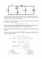
Anyway, here are my two sets of ODEs for this circuit, and the drawing that goes with it.
Note the symbolic cap voltage arrow is always up, and the symbolic cap current arrow is always down.
Note that i consider ground to be the bottom of the cap and inductor too so that is zero volts for my solutions and that makes the cap voltage numerically negative.
The top of the cap is considered symbolic positive always.
Also note the second circuit to the right is for comparison, it's a circuit you can use if you still have trouble with the first one. If you can do that circuit with the input switching from 0 to 5v you may get more insight into these circuits.
The inductor current is 'i' and the cap voltage is 'v' below..
switch on:
L*di/dt=E-i*RL
C*dv/dt=-v/R
(notice here iC=C*dv/dt the cap current is down so v must be negative because 'v' the cap voltage is positive symbolic with respect to ground and ground is the bottom of the cap)
switch off:
L*di/dt=v-i*RL
C*dv/dt=-i-v/R
Vavg during the last on/off cycle came out to be -3.565232376 volts.
Here is the output of the numerical solution after many cycles using C=1 and L=1 and your R and RL values...
[organization: 't' is time in seconds, {inductor current, cap voltage}]
t=99.810000 {0.5470675577,-3.577704524,1} (so this is time 99.81 seconds and iL=0.547 amps and vC=-3.578 volts)
t=99.820000 {0.5913749758,-3.574128607,1}
t=99.830000 {0.6352415277,-3.570556265,1}
t=99.840000 {0.6786716002,-3.566987494,1}
t=99.850000 {0.7216695362,-3.563422289,1}
t=99.860000 {0.7642396355,-3.559860648,1}
t=99.870000 {0.8063861554,-3.556302567,1}
t=99.880000 {0.8481133103,-3.552748042,1}
t=99.890000 {0.8894252731,-3.549197069,1}
t=99.900000 {0.930326175,-3.545649646,1}
t=99.910000 {0.885761531,-3.551181306,0}
t=99.920000 {0.8415875129,-3.556263966,0}
t=99.930000 {0.7978046796,-3.560901981,0}
t=99.940000 {0.7544135416,-3.565099708,0}
t=99.950000 {0.7114145605,-3.568861505,0}
t=99.960000 {0.6688081503,-3.572191729,0}
t=99.970000 {0.6265946772,-3.575094737,0}
t=99.980000 {0.5847744607,-3.577574885,0}
t=99.990000 {0.5433477736,-3.579636527,0}
t=100.000000 {0.5023148426,-3.581284018,0}
Just to note, the Laplace solutions come out pretty complicated because we have to include both the initial current for the inductor and initial voltage for the cap.
In the following, 'v' is initial cap voltage and 'i' is initial inductor current at start of half cycle...
switch on:
iL(s)=(i*s*L+E)/(s*RL+s^2*L)
vC(s)=(v*C*R)/(s*C*R+1)
Long equations are no longer from my favourite things.
You should know that Wikipedia is not always true. There are a lot of false things written there, and Wikipedia is a non-profit, not maintained organization, which does not give certainty of its posts' accuracy.
The voltage polarity across the resistor does not change.
The inductor voltage reverses because the inductance now acts like a voltage current-source to keep the current flowing in the same direction, but the voltage polarity across the resistor is unchanged, since the current direction does not change.
The voltage polarity across the inductor either changes or does not change according to how we view that very voltage. There are two cases: numeric and symbolic.
Numerically, the voltage definitely changes polarity for the reason you stated, but symbolically it does not change. In other words, we dont have to write -V we just have to write V, but once we solve for that voltage variable we may come up with V=+2 or V=-2 for example.. This was the only question that came up.
There actually may be times when we write "-V" in a symbolic equation, but it comes about because of a circuital law not because the voltage changes polarity as the solution time progresses. In that case if we do in fact write "-V" then "V" may still vary numerically either positive or negative and the influence in the equation will be the opposite because V is made negative in the equation itself.
Well if you are doing it symbolically then the cap current must stay the same.
This is a conflict that comes up now and then, whether to show the cap voltage as the symbolic value or numerical value. I believe if you show the cap current numerically then you will find that it changes direction, but when we say it symbolically it will always be the same and that is because the numerical solution will naturally produce a negative result so we dont have to try to force that symbolically. For example:
0=x+1
we dont have to change x to -x we just have to solve for it and then it comes out to a negative value.
Anyway, here are my two sets of ODEs for this circuit, and the drawing that goes with it.
Note the symbolic cap voltage arrow is always up, and the symbolic cap current arrow is always down.
Note that i consider ground to be the bottom of the cap and inductor too so that is zero volts for my solutions and that makes the cap voltage numerically negative.
The top of the cap is considered symbolic positive always.
Also note the second circuit to the right is for comparison, it's a circuit you can use if you still have trouble with the first one. If you can do that circuit with the input switching from 0 to 5v you may get more insight into these circuits.
The inductor current is 'i' and the cap voltage is 'v' below..
switch on:
L*di/dt=E-i*RL
C*dv/dt=-v/R
(notice here iC=C*dv/dt the cap current is down so v must be negative because 'v' the cap voltage is positive symbolic with respect to ground and ground is the bottom of the cap)
switch off:
L*di/dt=v-i*RL
C*dv/dt=-i-v/R
Vavg during the last on/off cycle came out to be -3.565232376 volts.
Here is the output of the numerical solution after many cycles using C=1 and L=1 and your R and RL values...
[organization: 't' is time in seconds, {inductor current, cap voltage}]
t=99.810000 {0.5470675577,-3.577704524,1} (so this is time 99.81 seconds and iL=0.547 amps and vC=-3.578 volts)
t=99.820000 {0.5913749758,-3.574128607,1}
t=99.830000 {0.6352415277,-3.570556265,1}
t=99.840000 {0.6786716002,-3.566987494,1}
t=99.850000 {0.7216695362,-3.563422289,1}
t=99.860000 {0.7642396355,-3.559860648,1}
t=99.870000 {0.8063861554,-3.556302567,1}
t=99.880000 {0.8481133103,-3.552748042,1}
t=99.890000 {0.8894252731,-3.549197069,1}
t=99.900000 {0.930326175,-3.545649646,1}
t=99.910000 {0.885761531,-3.551181306,0}
t=99.920000 {0.8415875129,-3.556263966,0}
t=99.930000 {0.7978046796,-3.560901981,0}
t=99.940000 {0.7544135416,-3.565099708,0}
t=99.950000 {0.7114145605,-3.568861505,0}
t=99.960000 {0.6688081503,-3.572191729,0}
t=99.970000 {0.6265946772,-3.575094737,0}
t=99.980000 {0.5847744607,-3.577574885,0}
t=99.990000 {0.5433477736,-3.579636527,0}
t=100.000000 {0.5023148426,-3.581284018,0}
Just to note, the Laplace solutions come out pretty complicated because we have to include both the initial current for the inductor and initial voltage for the cap.
In the following, 'v' is initial cap voltage and 'i' is initial inductor current at start of half cycle...
switch on:
iL(s)=(i*s*L+E)/(s*RL+s^2*L)
vC(s)=(v*C*R)/(s*C*R+1)
Long equations are no longer from my favourite things.
You should know that Wikipedia is not always true. There are a lot of false things written there, and Wikipedia is a non-profit, not maintained organization, which does not give certainty of its posts' accuracy.
Do you mean the development of the equations are too long or the result it's too long?
I know Wikipedia could be wrong some times, but in this case I tested the results in a simulation and the equation from wikipedia seems to be correct. Maybe the math procedure is wrong and the result it's correct, and that's why i'm making some mistake in my procedure to calculate the increments.
Okay.
But I was referring to your comment about the voltage across the resistor, not the inductor, which are not the same.
The voltage across the resistor does not change.
The values in the ODE's are as follows:
'v' is the symbolic cap voltage, positive on top negative on bottom, and that of course means numerically v comes out negative.
'i' is the inductor current flowing down through the inductor, and that means that when the switch is 'on' the voltage at the top of the inductor is numerically positive and when 'off' it is numerically negative.
Yes if we have a cap voltage increment that goes up then it must come down the same amount otherwise we are not yet in steady state. That means we only see that in steady state. HOWEVER, the sign of the increase is opposite to that of the decrease so dv/dt is positive one way and negative the other way.
I am not entirely sure i understand what you mean by the "off state current" in your previous post.
I'll take a closer look at this again later tonight.
Okay.
But I was referring to your comment about the voltage across the resistor, not the inductor, which are not the same.
The voltage across the resistor does not change.
In this circuit it does not change numerically because of the implied initial conditions. But it really follows the same idea though because a variable like "vR" or "Vr" does not imply any polarity so given another circuit or a slight change in startup conditions and we see it change numerically.
For example, suppose that someone came along and charged the cap up to +10 volts just before the circuit was turned on normally. That means that vR=+10 volts, but then after it starts and runs for a few seconds the cap voltage drops to -3.6 volts so that means that now vR=-3.6 volts. So here we see it change numerically (again just as the others) but not symbolically. That was the idea i was originally referring to.
In the ODE's the variable 'v' takes care of both the cap voltage and the resistor voltage, and the assumed polarity is positive up, but the numerical value can be set to anything to start which can be either polarity.
The values in the ODE's are as follows:
'v' is the symbolic cap voltage, positive on top negative on bottom, and that of course means numerically v comes out negative.
'i' is the inductor current flowing down through the inductor, and that means that when the switch is 'on' the voltage at the top of the inductor is numerically positive and when 'off' it is numerically negative.
Yes if we have a cap voltage increment that goes up then it must come down the same amount otherwise we are not yet in steady state. That means we only see that in steady state. HOWEVER, the sign of the increase is opposite to that of the decrease so dv/dt is positive one way and negative the other way.
I am not entirely sure i understand what you mean by the "off state current" in your previous post.
I'll take a closer look at this again later tonight.
Yes i took the second equations from each set of ODE's and then multiplied by either D or (1-D) as needed.
Then solved for the inductor current.
I guess that is what you did too.
If you like we can also go through the numerical solution steps, which are not very difficult although you may want to use a programming language to program in the steps so you can calculate the currents and voltages for any time from t=0 to whatever. It's only 2nd order so not too difficult.
We could also compute the actual symbolic time responses for all time but that's a bit more difficult. That gives us solutions like:
e^(-at)*(A*sin(wt)+B*cos(wt)) or similar.
[LATER]
I almost forgot to mention...
Going back to the ODE's, take the first equation of each set and that gives us two equations for L*di/dt, which we can also set the sum equal to zero after multiplying by D and (1-D) respectively, and then solve for 'v' the cap voltage. That should lead to the right result for the average output voltage knowing the average inductor current and of course the input voltage.
Here's what i got with E the input voltage:
Vo=-(RL*iL-D*E)/(D-1)
You can then combine your solution from before with the one you get here (above) and then you should be able to solve explicitly for the average Vout.
First try to reproduce the equation just above though, then go from there.
The numerical result i got matched the numerical result i got from the numerical ODE solving solution which was -3.57 volts approximately.
The symbolic result i got matched the Wikipedia entry as reproduced in the attachment here (copy from Wikipedia).
This leads me to believe that this Wikipedia entry is entirely correct.
It can also be written as:
Vo/Vi=((D-1)*D*R)/(RL+D^2*R-2*D*R+R)
Sorry i did not see your post as i saw the one after that one first.
When doing these kinds of calculations it is always assumed that the currents and voltage ramp up and down because the component values are large enough to enforce this. So dont worry about the wave shape for now just think of it as a straight ramp up or down.
Also, i added more to my previous post which i forgot to add before, and that should explain the entire solution. If you have any problem just let me know.
Basically there are some steps the way i did it:
1. Find the two sets of ODE's.
2. Sum the right hand side of two equations one from each set, after multiplying by D or (1-D) as appropriate for the switch state.
3. Since #2 above leads to two new equations one for iL and one for Vout, substitute the equation for iL into the equation for Vout and solve explicitly for the average Vout. This leads to the same symbolic equation as Wikipedia and also the numerical results match the ODE numerical solutions.
Hi!
If you like we can also go through the numerical solution steps, which are not very difficult although you may want to use a programming language to program in the steps so you can calculate the currents and voltages for any time from t=0 to whatever. It's only 2nd order so not too difficult. We could also compute the actual symbolic time responses for all time but that's a bit more difficult. That gives us solutions like: e^(-at)*(A*sin(wt)+B*cos(wt)) or similar.
I already did the numerical solution programming a loop in Python with Laplace Equations changed into time space equations with wxMaxima, just to simulate the process, but then I tried the same with PSIM.
But actually, I need the avg values from the steady state in order to get the minimum inductance and cap values for an Android App that calculates those parameters setting other values as frequency or Duty Cycle and vice versa. So, numerical solution maybe it's not an option. If I make some Circuit Simulator App like EveryCircuit I would use time equations for sure
I almost forgot to mention...
Going back to the ODE's, take the first equation of each set and that gives us two equations for L*di/dt, which we can also set the sum equal to zero after multiplying by D and (1-D) respectively, and then solve for 'v' the cap voltage. That should lead to the right result for the average output voltage knowing the average inductor current and of course the input voltage.
Here's what i got with E the input voltage:
Vo=-(RL*iL-D*E)/(D-1)
You can then combine your solution from before with the one you get here (above) and then you should be able to solve explicitly for the average Vout. First try to reproduce the equation just above though, then go from there.
The numerical result i got matched the numerical result i got from the numerical ODE solving solution which was -3.57 volts approximately.
The symbolic result i got matched the Wikipedia entry as reproduced in the attachment here (copy from Wikipedia).
In my past message I said that I tried to operate the inductor increment currents with the average current but didn't work it that time, looks like I make some mistake in the signs or something. Just changing one sign it worked!
Now, i redo step by step methodically and finally, i've got the same result
My mistake it seems it was a misunderstanding about signs when current flow changes in the Mesh System. Also i wasn't aware thant Cap current equation also changes the sign even if it's a Diferential Equation.
Now I wil try to add Source Parasital Resistance and Diode Drop Voltage.
 Facebook
 Google
 GitHub
 Linkedin


 119.1 KB Views: 4
")


