Buck-Boost Equations Problem With Inductor Parasital Resistance

Thread Starter

Tenma Chinen Pou

Joined Aug 24, 2018
40
When doing these kinds of calculations it is always assumed that the currents and voltage ramp up and down because the component values are large enough to enforce this. So dont worry about the wave shape for now just think of it as a straight ramp up or down.

Ok, I guess it would turn to 2n Order ODE appearing some natural exponential function, am I wrong?

Also, i added more to my previous post which i forgot to add before, and that should explain the entire solution. If you have any problem just let me know.

No problem, I just needed to better understand the sign trouble I've got.

Basically there are some steps the way i did it:
1. Find the two sets of ODE's.

Mixing the Current ODE's it's something that I wasn't

2. Sum the right hand side of two equations one from each set, after multiplying by D or (1-D) as appropriate for the switch state.

More than just multiplying, I integrated the ODEs in time from 0 to D·T and (1-D)·T, it's correct?

3. Since #2 above leads to two new equations one for iL and one for Vout, substitute the equation for iL into the equation for Vout and solve explicitly for the average Vout. This leads to the same symbolic equation as Wikipedia and also the numerical results match the ODE numerical
 

MrAl

Joined Jun 17, 2014
13,756
Hello again,

You're welcome, and i have to complement you on your solution layout as it is very clear and well presented. You dont know how mcny times i see such sloppy work i hate to have to help sometimes because it takes time just to figure out how they make their 7's or 1's and such :)
I'll answer your next post in a new post.
 

MrAl

Joined Jun 17, 2014
13,756
When doing these kinds of calculations it is always assumed that the currents and voltage ramp up and down because the component values are large enough to enforce this. So dont worry about the wave shape for now just think of it as a straight ramp up or down.

Ok, I guess it would turn to 2n Order ODE appearing some natural exponential function, am I wrong?

Also, i added more to my previous post which i forgot to add before, and that should explain the entire solution. If you have any problem just let me know.

No problem, I just needed to better understand the sign trouble I've got.

Basically there are some steps the way i did it:
1. Find the two sets of ODE's.

Mixing the Current ODE's it's something that I wasn't

2. Sum the right hand side of two equations one from each set, after multiplying by D or (1-D) as appropriate for the switch state.

More than just multiplying, I integrated the ODEs in time from 0 to D·T and (1-D)·T, it's correct?

3. Since #2 above leads to two new equations one for iL and one for Vout, substitute the equation for iL into the equation for Vout and solve explicitly for the average Vout. This leads to the same symbolic equation as Wikipedia and also the numerical results match the ODE numerical
Hi,

I had a sneaking suspicion that it could be the sign problem because these circuits are a little more tricky than say the buck circuit because the numerical sign of some of the variables changes while the sign of the symbolic var only changes due to circuit laws, and this gets confusing and so requires extra special care to get right. I've been doing these circuits for 100 years and i still have to be very careful :)

Yes, the true waveshape for this circuit is of the form with exponential modulator and sine and/or cosine factors, but in the analysis we seek to be able to avoid the true time solution and find ways to make it easier to comprehend. This is why we assume straight line solutions for some types of analysis, because that was one of the assumptions we wanted so we could make the analysis simpler, and of course for some things it works so why not use it.

Dont know why you would want to integrate, not sure why you want to do that but i guess you felt the need to do that. Maybe that is the better way but i would think we could equate derivatives just as well as we could equate integrals of those derivatives and thus assume equality. That was my assumption and i present the entire solution here so you can examine. We might be able to prove that straight line solution derivatives vary from the integral by only a constant factor, but you can look into this if you care to.

Here is the solution from start to finish using nodal and the ODE's as before.
Lower case for derivatives, upper case for actual current and voltage, and X1 is inductor current and X2 is cap voltage.
So x1 is the time derivative of X1, and x2 is the time derivative of X2, and since there are two sets one for 'on' and one for 'off' that gives us four derivatives where the first number is '1' for 'on' and '2' for off so:
x11 is the derivative of X1 for switch 'on',
x12 is the derivative of X2 for switch 'on',
x21 is the derivative of X1 for switch 'off',
x22 is the derivative of X2 for switch 'off'.

The solution in this way flows simply so it seems rather elegant, but see what you think personally.

[ALTERNATE SOLUTION]

Nodal ODE's switch on:
x11=E/L-RL*X1/L
x12=-X2/(R*C)

Nodal ODE's switch off:
x21=X2/L-RL*X1/L
x22=-X2/(R*C)-X1/C


Now start solution procedure assuming some equalities...

x12*D=-x22*(1-D)
-X2/(R*C)*D=-(-X2/(R*C)-X1/C)*(1-D)
solve for X1:
X1=X2/((D-1)*R)

x11*D=x21*(1-D)
(E/L-RL*X1/L)*D=-(X2/L-RL*X1/L)*(1-D)
solve for X2:
X2=-(RL*X1-D*E)/(D-1)

Now subst solution for X1 into this equation:
X2=-((RL*X2)/((D-1)*R)-D*E)/(D-1)
solve explicitly for X2:
X2=((D-1)*D*E*R)/(RL+D^2*R-2*D*R+R)
and that is the expression for the average output voltage X2.

Now subst that solution for X2 into the above solution for X1 and get:
X1=(D*E)/(RL+D^2*R-2*D*R+R)
and this is the expression for the average inductor current X1.
 

Thread Starter

Tenma Chinen Pou

Joined Aug 24, 2018
40
Hello again,

You're welcome, and i have to complement you on your solution layout as it is very clear and well presented. You dont know how mcny times i see such sloppy work i hate to have to help sometimes because it takes time just to figure out how they make their 7's or 1's and such :)
I'll answer your next post in a new post.
Thank you for the compliment. Try to present the problem I have clearly as possible it's the less I can do if someone helps me :)
 

Thread Starter

Tenma Chinen Pou

Joined Aug 24, 2018
40
I had a sneaking suspicion that it could be the sign problem because these circuits are a little more tricky than say the buck circuit because the numerical sign of some of the variables changes while the sign of the symbolic var only changes due to circuit laws, and this gets confusing and so requires extra special care to get right. I've been doing these circuits for 100 years and i still have to be very careful :)

I also had a misunderstanding with the average current, that's why even chaning the sign of some variables didn't show the same result as wikipedia at first time.

Yes, the true waveshape for this circuit is of the form with exponential modulator and sine and/or cosine factors, but in the analysis we seek to be able to avoid the true time solution and find ways to make it easier to comprehend. This is why we assume straight line solutions for some types of analysis, because that was one of the assumptions we wanted so we could make the analysis simpler, and of course for some things it works so why not use it.

I just find it weird that they always representing straight lines while an RL circuit with a step input needs a non linear equation.
But yes, for learning purposes should be ideal and without parasitic effects.


Dont know why you would want to integrate, not sure why you want to do that but i guess you felt the need to do that. Maybe that is the better way but i would think we could equate derivatives just as well as we could equate integrals of those derivatives and thus assume equality. That was my assumption and i present the entire solution here so you can examine.

I made the calculations methodically, so if I solve for inductor current diferential "diL", I pass the time diferential "dt" term to the other side mutiplying, then I integrate in time so appears the Duty Cycle x Period which represents the fraction of Period time wich is in ON State and (1-Duty Cycle) x Period for the OFF State.

But I see your point, even if we don't integrate, we could equate both diferential inductor currents and solve it.


[ALTERNATE SOLUTION]

Nodal ODE's switch on:
x11=E/L-RL*X1/L
x12=-X2/(R*C)

Nodal ODE's switch off:
x21=X2/L-RL*X1/L
x22=-X2/(R*C)-X1/C

Now start solution procedure assuming some equalities...

x12*D=-x22*(1-D) I wouldn't know that I must to do this step without using integration for example
-X2/(R*C)*D=-(-X2/(R*C)-X1/C)*(1-D)
solve for X1:
X1=X2/((D-1)*R)

x11*D=x21*(1-D)
(E/L-RL*X1/L)*D=-(X2/L-RL*X1/L)*(1-D)
solve for X2:
X2=-(RL*X1-D*E)/(D-1)

Now subst solution for X1 into this equation:
X2=-((RL*X2)/((D-1)*R)-D*E)/(D-1)
solve explicitly for X2:
X2=((D-1)*D*E*R)/(RL+D^2*R-2*D*R+R)
and that is the expression for the average output voltage X2.

Now subst that solution for X2 into the above solution for X1 and get:
X1=(D*E)/(RL+D^2*R-2*D*R+R)
and this is the expression for the average inductor current X1.


We might be able to prove that straight line solution derivatives vary from the integral by only a constant factor, but you can look into this if you care to.

I will have a look, but I'm a little bit in hurry to launch the App, I already calculate the buck-boost with whole parasitic resistances and drop voltages from switch and diode, and it fits pretty well with the simulation with a normal values.

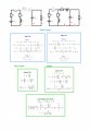
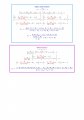
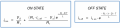
Here is the final result, maybe I should add the minimum capacity too.

Image 1.jpg
Image 2.jpg
By chance, your name won't be related with Artifial Inteligence, Deep Learning and that stuff?
 
Last edited:

MrAl

Joined Jun 17, 2014
13,756
Thank you for the compliment. Try to present the problem I have clearly as possible it's the less I can do if someone helps me :)
Hello again,

I wish everyone that asked questions here and elsewhere had that attitude!
It's so much easier to follow someone else's work when they present it so well and so it makes it much easier to help out.

**********

As to the equivalencies involving the derivatives and integrals, if i get a chance i will show the proof for this. It's simply a matter of showing what goes up must come down :) (referring to the straight line up and straight line down assumptions again)
If we have something that goes up from y1 to y2 in time D*T then in steady state it comes down by the same amount from y2 to y1 in time (1-D)*T.
The straight line approximations come into play partly because in these circuits we want a reasonably smooth output reasonably free from ripple. If you look at the definitions you can see this must be an assumption for an incremental view:
Definition:
i=C*dv/dt
transformation:
i=C*deltaV/deltaT

and here deltaV/deltaT is considered a constant so we end up with:
i=C*k

but i suppose there are other views too but keep in mind we are assuming small time increments too.

**********

I see you included Rs, Rd, and Vd too now.
If i get a chance later i will try to do this using the ODE method as before. It's a good exercise for me too because i dont do this stuff that much anymore and like to keep up with the theory a little bit.
One thing i see right off due to your very neatly drawn schematic, is that Rs combines easily with RL for the 'on' period, and Rd combines easily with RL for the 'off' period. With just those two we could come up with the equations directly from the previous ones. It's only Vd that complicates just a tiny bit more.

[LATER]
I gave this a quick try and the adjustments to the four ODE's were minimal so i went ahead and obtained the solution and checked it with the program solution.
The new ODE's were simple to modify as you can see:
switch on:
L*x1=E-X1*(RL+Rs)
C*x2=-X2/R

switch off:
L*x1=X2-X1*(RL+Rd)-Vd
C*x2=-X1-X2/R

and after doing the averaging calculations and plugging in values:
E=Vin=5, C=1, L=1, R=10, RL=0.5, Rs=0.5, Rd=0.5, Vd=0.5, D=0.5
i get these results:
--Numerical solutions from the full averaged solutions:
-- avg Vout: -3.214285714285714
-- avg iL: 0.64285714285714

--Numerical solutions from the numerical solver program:
-- avg Vout: -3.214161695
-- avg iL: 0.6428098613

It's a little interesting that Vout comes out very nearly 5 times the inductor current iL, and that happened last time too without the extra components. This might mean that we can find an averaged resistance too that relates the two.

[LATER LATER]
Real quick, including a little cap ESR results in a more complicated set of ODE's and much more complicated solution set, and with the cap ESR equal to 0.1 Ohms (and all the previous values) i get:
avg Vc=-3.1917
avg Vout=-3.1917

from the averaged equations but did not check this with the numerical solver method yet.

It is interesting to include the cap ESR because it is common to use this section of the circuit in a converter with feedback and then see how VERY significant the cap ESR is in the boost mode. The cap ESR is known to cause instability in boost converters.
Here we just see the magnitude of the average cap voltage decrease slightly and magnitude of Vout increase very slightly from that without the cap ESR because it's simply a feed forward converter as is. [Correction: Vout decreased slightly too].
 
Last edited:

Thread Starter

Tenma Chinen Pou

Joined Aug 24, 2018
40
Hi!

I wish everyone that asked questions here and elsewhere had that attitude!
It's so much easier to follow someone else's work when they present it so well and so it makes it much easier to help out.

Thanks :) , my College Teachers never compliment me like this, maybe I was asking too much!

As to the equivalencies involving the derivatives and integrals, if i get a chance i will show the proof for this. It's simply a matter of showing what goes up must come down :) (referring to the straight line up and straight line down assumptions again)
If we have something that goes up from y1 to y2 in time D*T then in steady state it comes down by the same amount from y2 to y1 in time (1-D)*T.


This part I've realized while I was trying to solve Buck-Boost circuit, it's not possible to have an Steady State without turning back to the same point.

The straight line approximations come into play partly because in these circuits we want a reasonably smooth output reasonably free from ripple. If you look at the definitions you can see this must be an assumption for an incremental view:
Definition:
i=C*dv/dt
transformation:
i=C*deltaV/deltaT

and here deltaV/deltaT is considered a constant so we end up with:
i=C*k

but i suppose there are other views too but keep in mind we are assuming small time increments too.

I don't understand this, what do you mean by "Small Time Increments" ?

I see you included Rs, Rd, and Vd too now.
If i get a chance later i will try to do this using the ODE method as before. It's a good exercise for me too because i dont do this stuff that much anymore and like to keep up with the theory a little bit.
One thing i see right off due to your very neatly drawn schematic, is that Rs combines easily with RL for the 'on' period, and Rd combines easily with RL for the 'off' period. With just those two we could come up with the equations directly from the previous ones. It's only Vd that complicates just a tiny bit more.

Thankyou! I will post my results to.

[LATER]
I gave this a quick try and the adjustments to the four ODE's were minimal so i went ahead and obtained the solution and checked it with the program solution.
The new ODE's were simple to modify as you can see:
switch on:
L*x1=E-X1*(RL+Rs)
C*x2=-X2/R

switch off:
L*x1=X2-X1*(RL+Rd)-Vd
C*x2=-X1-X2/R

and after doing the averaging calculations and plugging in values:
E=Vin=5, C=1, L=1, R=10, RL=0.5, Rs=0.5, Rd=0.5, Vd=0.5, D=0.5

You don't need the frequency form the numerical solver program?

i get these results:
--Numerical solutions from the full averaged solutions:
-- avg Vout: -3.214285714285714
-- avg iL: 0.64285714285714

--Numerical solutions from the numerical solver program:
-- avg Vout: -3.214161695
-- avg iL: 0.6428098613

My Results:
--Numerical solutions from the full averaged solutions:
-- avg Vout: -3.214285714285714 (Yours: Exactly the same)
-- avg iL: 0.64285714285714
28 (Yours: 0.64285714285714)


Frequency = 100kHz
--Numerical solutions from the numerical solver program:
-- avg Vout: -3.1945872 (Yours : -3.214161695)
-- avg iL: 0.67353179 (Yours : 0.6428098613)


Maybe PSIM simlulation makes some slight error making the avg.

It's a little interesting that Vout comes out very nearly 5 times the inductor current iL, and that happened last time too without the extra components. This might mean that we can find an averaged resistance too that relates the two.

How is that possible? Average Inductor Current remains the same and Ouput Voltage depends on that current and the other components, but Inductor Current doesn't depend on the component values.

[LATER LATER]
Real quick, including a little cap ESR results in a more complicated set of ODE's and much more complicated solution set, and with the cap ESR equal to 0.1 Ohms (and all the previous values) i get:
avg Vc=-3.1917
avg Vout=-3.2233

from the averaged equations but did not check this with the numerical solver method yet.

It is interesting to include the cap ESR because it is common to use this section of the circuit in a converter with feedback and then see how VERY significant the cap ESR is in the boost mode. The cap ESR is known to cause instability in boost converters.
Here we just see the magnitude of the average cap voltage decrease slightly and magnitude of Vout increase very slightly from that without the cap ESR because it's simply a feed forward converter as is.

Wow, that's important change, I will put the Cap inner resistance to the equation, thanks for notice me that, Thanks a lot for helping me! :)
 

MrAl

Joined Jun 17, 2014
13,756
Hi!

I wish everyone that asked questions here and elsewhere had that attitude!
It's so much easier to follow someone else's work when they present it so well and so it makes it much easier to help out.

Thanks :) , my College Teachers never compliment me like this, maybe I was asking too much!

As to the equivalencies involving the derivatives and integrals, if i get a chance i will show the proof for this. It's simply a matter of showing what goes up must come down :) (referring to the straight line up and straight line down assumptions again)
If we have something that goes up from y1 to y2 in time D*T then in steady state it comes down by the same amount from y2 to y1 in time (1-D)*T.


This part I've realized while I was trying to solve Buck-Boost circuit, it's not possible to have an Steady State without turning back to the same point.

The straight line approximations come into play partly because in these circuits we want a reasonably smooth output reasonably free from ripple. If you look at the definitions you can see this must be an assumption for an incremental view:
Definition:
i=C*dv/dt
transformation:
i=C*deltaV/deltaT

and here deltaV/deltaT is considered a constant so we end up with:
i=C*k

but i suppose there are other views too but keep in mind we are assuming small time increments too.

I don't understand this, what do you mean by "Small Time Increments" ?

I see you included Rs, Rd, and Vd too now.
If i get a chance later i will try to do this using the ODE method as before. It's a good exercise for me too because i dont do this stuff that much anymore and like to keep up with the theory a little bit.
One thing i see right off due to your very neatly drawn schematic, is that Rs combines easily with RL for the 'on' period, and Rd combines easily with RL for the 'off' period. With just those two we could come up with the equations directly from the previous ones. It's only Vd that complicates just a tiny bit more.

Thankyou! I will post my results to.

[LATER]
I gave this a quick try and the adjustments to the four ODE's were minimal so i went ahead and obtained the solution and checked it with the program solution.
The new ODE's were simple to modify as you can see:
switch on:
L*x1=E-X1*(RL+Rs)
C*x2=-X2/R

switch off:
L*x1=X2-X1*(RL+Rd)-Vd
C*x2=-X1-X2/R

and after doing the averaging calculations and plugging in values:
E=Vin=5, C=1, L=1, R=10, RL=0.5, Rs=0.5, Rd=0.5, Vd=0.5, D=0.5

You don't need the frequency form the numerical solver program?

i get these results:
--Numerical solutions from the full averaged solutions:
-- avg Vout: -3.214285714285714
-- avg iL: 0.64285714285714

--Numerical solutions from the numerical solver program:
-- avg Vout: -3.214161695
-- avg iL: 0.6428098613

My Results:
--Numerical solutions from the full averaged solutions:
-- avg Vout: -3.214285714285714 (Yours: Exactly the same)
-- avg iL: 0.64285714285714
28 (Yours: 0.64285714285714)


Frequency = 100kHz
--Numerical solutions from the numerical solver program:
-- avg Vout: -3.1945872 (Yours : -3.214161695)
-- avg iL: 0.67353179 (Yours : 0.6428098613)


Maybe PSIM simlulation makes some slight error making the avg.

It's a little interesting that Vout comes out very nearly 5 times the inductor current iL, and that happened last time too without the extra components. This might mean that we can find an averaged resistance too that relates the two.

How is that possible? Average Inductor Current remains the same and Ouput Voltage depends on that current and the other components, but Inductor Current doesn't depend on the component values.

[LATER LATER]
Real quick, including a little cap ESR results in a more complicated set of ODE's and much more complicated solution set, and with the cap ESR equal to 0.1 Ohms (and all the previous values) i get:
avg Vc=-3.1917
avg Vout=-3.2233

from the averaged equations but did not check this with the numerical solver method yet.

It is interesting to include the cap ESR because it is common to use this section of the circuit in a converter with feedback and then see how VERY significant the cap ESR is in the boost mode. The cap ESR is known to cause instability in boost converters.
Here we just see the magnitude of the average cap voltage decrease slightly and magnitude of Vout increase very slightly from that without the cap ESR because it's simply a feed forward converter as is.

Wow, that's important change, I will put the Cap inner resistance to the equation, thanks for notice me that, Thanks a lot for helping me! :)

Hello again

I typed this offline i hope you can read it ok.

Small time increments relative to the fastest time constant in the circuit.
However, i think there is another relationship that shows how this works in
a more explicite manner. That is the relationship between the average of
a rising and falling exponential and the average of a rising and falling
straight line ramp. I think they might be the same but dont remember exactly.
We could look into this and try to prove it i guess if you like. It would
mean that the average of say a voltage in a circuit that has rising and
falling exponentials would have the same average even if they were straight
lines ramping up and down.


Regarding your question:
"You don't need the frequency form the numerical solver program?"
Not entirely sure what you mean here. The ODE's can be solved
numerically as is using a numerical solver method like Heuns or
something else. I happen to like using a variation of that method
which i call Taylors Method because it mimiks what we do when finding
a Taylor Series. There are many other methods though.
How did you think of soloving them using a 'frequency' method?

"How is that possible? Average Inductor Current remains the same and Ouput Voltage depends on that current and the other components, but Inductor Current doesn't depend on the component values."
I have not looked into it that much yet doing some other things.


Regarding the cap ESR:
"Wow, that's important change, I will put the Cap inner resistance to the equation, thanks for notice me that, Thanks a lot for helping me! :)"
I thought you might like to think about that. You might even find it easier to calculate using your mesh equations.


Also:
The Taylor Method (and other methods) are just special integrating techniques used on sets of ODE's.
We could look at this method and see how simple it is, but i'd like to hear about your 'frequency'
method too if possible.
 

Thread Starter

Tenma Chinen Pou

Joined Aug 24, 2018
40
Small time increments relative to the fastest time constant in the circuit.
However, i think there is another relationship that shows how this works in
a more explicite manner. That is the relationship between the average of
a rising and falling exponential and the average of a rising and falling
straight line ramp. I think they might be the same but dont remember exactly.
We could look into this and try to prove it i guess if you like. It would
mean that the average of say a voltage in a circuit that has rising and
falling exponentials would have the same average even if they were straight
lines ramping up and down.

Could be possible, since the rising exponential have much area than straight line and falling exponential have less area than straigh falling line. Maybe I can test it later with wxMaxima.

Regarding your question:
"You don't need the frequency form the numerical solver program?"
Not entirely sure what you mean here.
The ODE's can be solved
numerically as is using a numerical solver method like Heuns or
something else. I happen to like using a variation of that method
which i call Taylors Method because it mimiks what we do when finding
a Taylor Series. There are many other methods though.
How did you think of soloving them using a 'frequency' method?


Sorry, here I wanted to say period, the inverse of frequency. I thought that when you said "numerically" it was using some software that make the calculations in time. So, it needs an ON period input and then OFF period input, wich the total is the period.

Heuns/ Euler's or Taylor's Method... I've never learned Such a things at my college, I've just seen in a movie.
Which degree did you coursed if can I ask?


"How is that possible? Average Inductor Current remains the same and Ouput Voltage depends on that current and the other components, but Inductor Current doesn't depend on the component values."
I have not looked into it that much yet doing some other things.

Inductor and Diode Resistance shouldn't change the inductor avg current, reducing the value?

Regarding the cap ESR:
"Wow, that's important change, I will put the Cap inner resistance to the equation, thanks for notice me that, Thanks a lot for helping me! :)"
I thought you might like to think about that. You might even find it easier to calculate using your mesh equations.

Actually, I've tried to redo the math, and even if I take off the other parasitic components, I couldn't solve it.

The Taylor Method (and other methods) are just special integrating techniques used on sets of ODE's.
We could look at this method and see how simple it is, but i'd like to hear about your 'frequency'
method too if possible.

That "Frequency Method" it was just using laplace transform to have ON and OFF inductor current equations, and iterate until it reaches the steady state aproximatelly, and then I can use it to get the Output Voltage or whatever. That's what I thought that you were referring to Numerical Solution, I guess is not.

Here is an example of a switched RL circuit, which haves R1 in ON State, and discharges on R2 in OFF State.

upload_2018-9-1_1-34-13.png

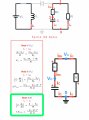
And here is the parasitic resistance from capacitor. Again, I can't find the problem :(
RePostCap.jpg
 

MrAl

Joined Jun 17, 2014
13,756
Small time increments relative to the fastest time constant in the circuit.
However, i think there is another relationship that shows how this works in
a more explicite manner. That is the relationship between the average of
a rising and falling exponential and the average of a rising and falling
straight line ramp. I think they might be the same but dont remember exactly.
We could look into this and try to prove it i guess if you like. It would
mean that the average of say a voltage in a circuit that has rising and
falling exponentials would have the same average even if they were straight
lines ramping up and down.

Could be possible, since the rising exponential have much area than straight line and falling exponential have less area than straigh falling line. Maybe I can test it later with wxMaxima.

Regarding your question:
"You don't need the frequency form the numerical solver program?"
Not entirely sure what you mean here.
The ODE's can be solved
numerically as is using a numerical solver method like Heuns or
something else. I happen to like using a variation of that method
which i call Taylors Method because it mimiks what we do when finding
a Taylor Series. There are many other methods though.
How did you think of soloving them using a 'frequency' method?


Sorry, here I wanted to say period, the inverse of frequency. I thought that when you said "numerically" it was using some software that make the calculations in time. So, it needs an ON period input and then OFF period input, wich the total is the period.

Heuns/ Euler's or Taylor's Method... I've never learned Such a things at my college, I've just seen in a movie.
Which degree did you coursed if can I ask?


"How is that possible? Average Inductor Current remains the same and Ouput Voltage depends on that current and the other components, but Inductor Current doesn't depend on the component values."
I have not looked into it that much yet doing some other things.

Inductor and Diode Resistance shouldn't change the inductor avg current, reducing the value?

Regarding the cap ESR:
"Wow, that's important change, I will put the Cap inner resistance to the equation, thanks for notice me that, Thanks a lot for helping me! :)"
I thought you might like to think about that. You might even find it easier to calculate using your mesh equations.

Actually, I've tried to redo the math, and even if I take off the other parasitic components, I couldn't solve it.

The Taylor Method (and other methods) are just special integrating techniques used on sets of ODE's.
We could look at this method and see how simple it is, but i'd like to hear about your 'frequency'
method too if possible.

That "Frequency Method" it was just using laplace transform to have ON and OFF inductor current equations, and iterate until it reaches the steady state aproximatelly, and then I can use it to get the Output Voltage or whatever. That's what I thought that you were referring to Numerical Solution, I guess is not.

Here is an example of a switched RL circuit, which haves R1 in ON State, and discharges on R2 in OFF State.

View attachment 159095

And here is the parasitic resistance from capacitor. Again, I can't find the problem :(
View attachment 159096
"Could be possible, since the rising exponential have much area than straight line and falling exponential have less area than straigh falling line. Maybe I can test it later with wxMaxima."
Yes good idea. The exponentials have to be those that are from a circuit in steady state. I might do this too just for the exercise.

"Sorry, here I wanted to say period, the inverse of frequency. I thought that when you said "numerically" it was using some software that make the calculations in time. So, it needs an ON period input and then OFF period input, wich the total is the period."
Oh i see now what you meant, yes that's of interest too. You meant what was the input frequency.
I used 50Hz just for the trial (50 percent duty cycle), but i also used C=1 and L=1 not the values you used. I could use your values too
and then your frequeny choice. One thing we need to ensure is we get continuous operation as i assume that was the mode of operation of interest all along here.

"Heuns/ Euler's or Taylor's Method... I've never learned Such a things at my college, I've just seen in a movie.
Which degree did you coursed if can I ask?"

I used a fourth degree method. However, you could probably just use Euler's Method which is a first order Taylor's:
y[n+1]=y[n]+dy/dt*h

where
y[n] is the current value of the solution,
y[n+1] is the next value of the solution,
dy/dt is the derivative of y at y[n],
h is the time increment, usually made small.
The whole idea is simple, and that is that when you look at a ramp one time increment in the future the value of y
is the previous value of y plus the slope times the time increment.
The second order Taylor's would just include another derivative and a constant and a multiplication by h^2:
y[n+1]=y[n]+dy/dt*h+d2y/dt2*h*h/2

so it's more accurate, but we have to be a little careful how we get that second derviative d2y/dt2 and watch out for
numerical instability.
In any of these, the smaller the increment 'h' is the better the approximation, but there is a limit where if h is
too small we get numerical instability and that messes up the whole solution badly.

Another method is Runge Kutta which seems to be popular.

The common actual use of these methods is that you calculate with an Nth order method and then calculate with an
(N+1)th order method and then compare results and they should be very similar.

"Inductor and Diode Resistance shouldn't change the inductor avg current, reducing the value?"
I havent looked into that yet.

"Actually, I've tried to redo the math, and even if I take off the other parasitic components, I couldn't solve it"
Hmmm, i wonder what did not work. Did you try Nodal then?

"That "Frequency Method" it was just using laplace transform to have ON and OFF inductor current equations, and iterate until it reaches the steady state aproximatelly, and then I can use it to get the Output Voltage or whatever. That's what I thought that you were referring to Numerical Solution, I guess is not."
Oh i see. Well i just went at it with a tried and proven numerical method for ODE's which does not require Laplace Transforms.
Going though the exercise with Laplace is good too though.
One of the advantages of the special numerical integration techniques is that the same code can solve every set of ODE's, except of course
for the writing of the ODE set itself.

*********

I saw your recent example equations and you reminded me that we can probably use a cap and resistor charging and
discharging to show that the rising and falling exponentials have the same or similar average as a ramp that goes
up and down too. I might try this soon.

BTW, it's always nice to see people interested in this stuff :)
 

Thread Starter

Tenma Chinen Pou

Joined Aug 24, 2018
40
Oh i see now what you meant, yes that's of interest too. You meant what was the input frequency.
I used 50Hz just for the trial (50 percent duty cycle), but i also used C=1 and L=1 not the values you used. I could use your values too
and then your frequeny choice. One thing we need to ensure is we get continuous operation as i assume that was the mode of operation of interest all along here.


Ok I see, you took that large Cap and Inductor values to ensure the Continuous Operation. In my case, I set a high frequency and moderated Cap and inductor values.

I used a fourth degree method. However, you could probably just use Euler's Method which is a first order Taylor's

Ha ha, by degree I meant career, sorry, I will have a look to the method.

Hmmm, i wonder what did not work. Did you try Nodal then?

I've tried Mesh and Nodal. I put in red the new variables from de Cap to better follow the steps.
I think I've a concept error in the nodal method, did you see the procedure? It is correct?


*********
BTW, it's always nice to see people interested in this stuff :)

Since I calculated the equations for the 555 Timer in Astable mode to make an oscillator, I've seen that even a source resistor could change the output frequency a couple of KiloHertz, so it's not just because of interest or precision, it's because reality it's quite far from theory. Then if I want some DC-DC converter, I want to know exactly what I'm doing, on the contrary I get nervous haha.

Hope you could find the problem on my procedure, I will still triying to find what I'm doing wrong again.
 

MrAl

Joined Jun 17, 2014
13,756
Oh i see now what you meant, yes that's of interest too. You meant what was the input frequency.
I used 50Hz just for the trial (50 percent duty cycle), but i also used C=1 and L=1 not the values you used. I could use your values too
and then your frequeny choice. One thing we need to ensure is we get continuous operation as i assume that was the mode of operation of interest all along here.


Ok I see, you took that large Cap and Inductor values to ensure the Continuous Operation. In my case, I set a high frequency and moderated Cap and inductor values.

I used a fourth degree method. However, you could probably just use Euler's Method which is a first order Taylor's

Ha ha, by degree I meant career, sorry, I will have a look to the method.

Hmmm, i wonder what did not work. Did you try Nodal then?

I've tried Mesh and Nodal. I put in red the new variables from de Cap to better follow the steps.
I think I've a concept error in the nodal method, did you see the procedure? It is correct?


*********
BTW, it's always nice to see people interested in this stuff :)

Since I calculated the equations for the 555 Timer in Astable mode to make an oscillator, I've seen that even a source resistor could change the output frequency a couple of KiloHertz, so it's not just because of interest or precision, it's because reality it's quite far from theory. Then if I want some DC-DC converter, I want to know exactly what I'm doing, on the contrary I get nervous haha.

Hope you could find the problem on my procedure, I will still triying to find what I'm doing wrong again.
Hello again,

Oh i must have mistaken your equations for something else. I see them now, that you were doing the circuit with Rc in it.
I will look over your equations and see if they were correct or not and let you know soon.
The nodal equations i did included RL, Rs, Rd, Vd, and Rc but with just Rc it will be much simpler.

[LATER]
I took a quick look at your nodal equations, and i have to ask why do you want to include Vo (the output voltage i presume) in the equations, such as for Vc ?
If we dont know what Vo is we cant know what Vc is.
Can you explain a little?
 
Last edited:

Thread Starter

Tenma Chinen Pou

Joined Aug 24, 2018
40
Hi

Oh i must have mistaken your equations for something else. I see them now, that you were doing the circuit with Rc in it.
I will look over your equations and see if they were correct or not and let you know soon.
The nodal equations i did included RL, Rs, Rd, Vd, and Rc but with just Rc it will be much simpler.

Yes, I remove all what was unnecessary to better understand what's going on in the nodals equations.

I took a quick look at your nodal equations, and i have to ask why do you want to include Vo (the output voltage i presume) in the equations, such as for Vc ? If we dont know what Vo is we cant know what Vc is.

I just follow the Nodal rules, and Vo (Output Voltage) appeared as you seen.
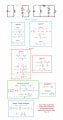
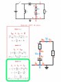
I left here a better explanation of the nodal equations.

I put in a GREEN BOX the Nodal Equations result wich actually works, but they doesn't care about Cap Resistance, so I assume that the procedure it's no correct, because you said Out Put Voltage decreases a bit because of Cap Resistance, am I wrong?


RePostCap.jpg
RePostCap2.jpg
 

MrAl

Joined Jun 17, 2014
13,756
Hi

Oh i must have mistaken your equations for something else. I see them now, that you were doing the circuit with Rc in it.
I will look over your equations and see if they were correct or not and let you know soon.
The nodal equations i did included RL, Rs, Rd, Vd, and Rc but with just Rc it will be much simpler.

Yes, I remove all what was unnecessary to better understand what's going on in the nodals equations.

I took a quick look at your nodal equations, and i have to ask why do you want to include Vo (the output voltage i presume) in the equations, such as for Vc ? If we dont know what Vo is we cant know what Vc is.

I just follow the Nodal rules, and Vo (Output Voltage) appeared as you seen.
I left here a better explanation of the nodal equations.

I put in a GREEN BOX the Nodal Equations result wich actually works, but they doesn't care about Cap Resistance, so I assume that the procedure it's no correct, because you said Out Put Voltage decreases a bit because of Cap Resistance, am I wrong?


View attachment 159187
View attachment 159190
Hello again,

Well thanks for the very clear drawings again, even more clear then before which is really nice to see. It helps a lot to see good drawings. You would not believe some of the drawings i have seen in the past which were so hard to read it made it virtually impossible to follow the logic.

Maybe i do not understand your goals for this new problem, because it looks to me that you still have one too many variables in your solution. However, you might be able to clear this up by showing your solution for the average Vo (Vout).
Variables that we must use are the inductor current and capacitor voltage and one derivative for each, but we dont need Vo except to solve for that later based on the solutions we get for the inductor current and cap voltage. But i'll wait to hear more from you about this.
In any case, see if you can solve for the average Vo, which is what we usually go after as a minimum.

Oh yeah BTW i checked the commonly accepted solution to the averaging technique and one of the rationales is that the derivative of the average of any variable is zero, so the general solution is:
x=Kon*X*D+Koff*X*(1-D)

where X is the variable and (lower case) x is the derivative, and after setting x=0 (as explained above) we get of course:
0=Kon*X*D+Koff*X*(1-D)

and that is part of the procedure i had shown previously. Now that there is no derivative there is nothing to integrate.
Dont worry about this too much right now though i would rather you concentrate on the solution to the average Vo.

The form of the equations i would write would be as:
di/dt=f1(iL,vC)
dv/dt=f2(iL,vC)

and NOT as:
di/dt=f1(iL,vC,Vo)
dv/dt=ft(iL,vC,Vo)

because Vo does not need to be an input variable. I'll wait for your solution however to see your point of view here.
 

Thread Starter

Tenma Chinen Pou

Joined Aug 24, 2018
40
Maybe i do not understand your goals for this new problem, because it looks to me that you still have one too many variables in your solution. However, you might be able to clear this up by showing your solution for the average Vo (Vout).
Variables that we must use are the inductor current and capacitor voltage and one derivative for each, but we dont need Vo except to solve for that later based on the solutions we get for the inductor current and cap voltage. But i'll wait to hear more from you about this.
In any case, see if you can solve for the average Vo, which is what we usually go after as a minimum.


The problem was, even if I use the new Node Equations, the Vo (Voltage Output) doesn't change at all using the equations inside Green Square, and if I use the other Node Equations which are not inside the Green Square, they appear different results, starting from the Average Current which it's not correct because setting RC = 0 the equation must to be same as Cap with no Inner Resistance. I shown in the past Images, but I will show you again step by step why doesn't work.
 

Thread Starter

Tenma Chinen Pou

Joined Aug 24, 2018
40
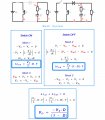
Here is the Vo(Ouput Voltage) with the Capacitor Inner Resistance added to the circuit.
As you can see, Nodes was not necessary, that's why look suspicious at first.

Then, if I make the Nodes, the Inductor Average Current would be incorrect too, as I will show you in the next post.

Repost Cap Mesh.jpg
 

Thread Starter

Tenma Chinen Pou

Joined Aug 24, 2018
40
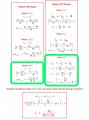
Here is the first method, taking the last equation in the Green Box, to solve the Inductor Average Current, but look likes to be the same without the Capacitor Inner Resistance. Then, in the next post, I will show you that using the other equations, the result is slightly different, but it's not correct neither.
Repost Cap Node Method 1.jpg
 

MrAl

Joined Jun 17, 2014
13,756
Here is the first method, taking the last equation in the Green Box, to solve the Inductor Average Current, but look likes to be the same without the Capacitor Inner Resistance. Then, in the next post, I will show you that using the other equations, the result is slightly different, but it's not correct neither.
View attachment 159212
Hi,

Ok so you are saying it seems hard to solve for either the average inductor current or the average capacitor voltage?

I have to ask again though, in your equation:
iL=-Vo/(R*(1-D))

how do you intend to get the numerical value for iL when you dont know Vo yet?
It is true that the average Vo does not change, but we still must know what it is to be able to get iL in that equation. That's why it is better to try to eliminate it altogether.

The actual average iL will include the variable Rc which is the cap ESR value.
 

Thread Starter

Tenma Chinen Pou

Joined Aug 24, 2018
40
Ok so you are saying it seems hard to solve for either the average inductor current or the average capacitor voltage?
Yes, both of them.

I have to ask again though, in your equation:
iL=-Vo/(R*(1-D))
how do you intend to get the numerical value for iL when you dont know Vo yet?
It is true that the average Vo does not change, but we still must know what it is to be able to get iL in that] equation. That's why it is better to try to eliminate it altogether.


I just need the "iL" equation to substitute inside the inductor current increments when we add more parasitic components, just for that. Now look unnecessary because we just took the cap inner resistance as parasitic component, but shows that the procedure fails at some point, which is what i'm trying to figure it out.


The actual average iL will include the variable Rc which is the cap ESR value

That what I expected, but I didn't appear that variable in the Average "iL"

Did you get the resulting equations?
 
Top