Broken guitar pedal project (Bitsbox muff)

Thread Starter

BrokenBones108

Joined Nov 25, 2022
16
Hello,
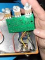
About a year ago I bought a Muff Guitar pedal project from Bitsbox. It was working well untill it broke last week.

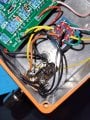
I took it apart and noticed the ground wire coming from the output has been pulled out of the board (the output became lose and must have spun enough to pull this off). Now I have reattached it passes through the sound when it is off, but when I press the switch for distortion there is no output. The led lights up but I get nothing out of the amp. I am presuming the ground wire has contacted something it shouldn't have, and now something is blown.

I have tested the majority of the circuit and everything seems to have power other than Diode2, D2( see wiring diagram). There is around 8v one side of it but nothing on the other.

I don't know enough to say that is the problem and was wondering if someone could tell me if this sounds like the problem or just a red hering.

Cheers,
ChrisScreenshot_20221125-233122_Drive.jpg20221125_211257.jpg
 

Audioguru again

Joined Oct 21, 2019
6,673
It is normal for the anode of D2 to have no voltage.
I guess that D2 and D4 should have the same voltages.
The cathode of D2 seems to be much too high indicating that R11, R14 and/or Q2 is burned out.
Post the DC voltages on the Q2 and Q3 pins when there is no input signal.
 

Thread Starter

BrokenBones108

Joined Nov 25, 2022
16

Thread Starter

BrokenBones108

Joined Nov 25, 2022
16
It is normal for the anode of D2 to have no voltage.
I guess that D2 and D4 should have the same voltages.
The cathode of D2 seems to be much too high indicating that R11, R14 and/or Q2 is burned out.
Post the DC voltages on the Q2 and Q3 pins when there is no input signal.
Hello, and thank you for your response.
Q2: 3.94v
Q3: 3.9v
 

Audioguru again

Joined Oct 21, 2019
6,673
The two transistors each have 3 pins. Then post the 6 voltages and say what they are at (base, emitter and collector).
Also, what is the DC power supply voltage with the circuit turned on?
 

MisterBill2

Joined Jan 23, 2018
18,175
First, the circuit shown does not include whatever switching arrangement is provided to bypass the circuit when the power is off. So we do not have any information about the actual system.
The very first thing to check is to see if some other portion of the connection traces on the board were damaged when the output wire was pulled off of the board. An examination of the foil side of the circuit board should reveal the problem. There may be a broken runner that we do not see.
 

MrChips

Joined Oct 2, 2009
30,711
In guitar FX stomp boxes, the power switch is often in the 1/4" input jack. Unplug the guitar from the FX box and the 9V battery power is disconnected.
 

MrChips

Joined Oct 2, 2009
30,711
Check the voltages on the base, collector and emitter of transistor Q4.

Post another photograph from above without the blue lines added. We want to be able to read the resistor colour bands.
 

Thread Starter

BrokenBones108

Joined Nov 25, 2022
16
First, the circuit shown does not include whatever switching arrangement is provided to bypass the circuit when the power is off. So we do not have any information about the actual system.
The very first thing to check is to see if some other portion of the connection traces on the board were damaged when the output wire was pulled off of the board. An examination of the foil side of the circuit board should reveal the problem. There may be a broken runner that we do not see.
Hello,
Thank you for your response.
Please see the attached photos from the foil side of the board.
Now this was my first attempt at this so I can't say if I caught the bored with the soldering iron when putting it together. But there seems to be some blackness around C3 and Q4.
 

Attachments

Thread Starter

BrokenBones108

Joined Nov 25, 2022
16
Check the voltages on the base, collector and emitter of transistor Q4.

Post another photograph from above without the blue lines added. We want to be able to read the resistor colour bands.
Hello,
I believe you are right that the 1/4 jack's complete some of the circuit as the LED does not light up when they are removed.
Sorry for my ignorance here but, flat side of Q4 facing me, from left to right, 7.6v, 6.5v and 4.1v.
I have also attached the guide for building this pedal if it helps.
 

Attachments

MrChips

Joined Oct 2, 2009
30,711
Thanks for posting the photos and info.

The voltages on Q4, 2N5088 are seriously wrong.
Remove the transistor Q4 and measure the voltages at the empty Q4 pads on the board.
 

Thread Starter

BrokenBones108

Joined Nov 25, 2022
16
Thanks for posting the photos and info.

The voltages on Q4, 2N5088 are seriously wrong.
Remove the transistor Q4 and measure the voltages at the empty Q4 pads on the board.
To be fair this may be the way I am testing it. Based on what a friend told me a while ago, I am putting the positive probe of the multi meter on the positive cable from the 9v, then the negative probe on each connector on Q4. If this is not correct let me know and I will do some reading up.
Thanks for you help with this I really appreciate it.
 

MrChips

Joined Oct 2, 2009
30,711
To be fair this may be the way I am testing it. Based on what a friend told me a while ago, I am putting the positive probe of the multi meter on the positive cable from the 9v, then the negative probe on each connector on Q4. If this is not correct let me know and I will do some reading up.
Thanks for you help with this I really appreciate it.
Ok.

Please put the negative (black) meter probe on the negative terminal of the battery. Use the positive (red) probe to take voltage measurements.
 

MrSalts

Joined Apr 2, 2020
2,767
They are close I will give you that, but the are not actually touching. This has been working for about a year so I am presuming the fault it to do with the cable disconnecting.
A lot of the vintage pedals were "positive ground". These typically were based on PNP germanium transistors. This one is a negative ground but may cause problems if chained with positive ground pedals that are externally powered by a single supply (not battery).
 
Last edited:

MrSalts

Joined Apr 2, 2020
2,767
They are close I will give you that, but the are not actually touching. This has been working for about a year so I am presuming the fault it to do with the cable disconnecting.
The problem could have occurred because you (or someone) rotated the cable as they plugged/unplugged a cable. There are no tabs on your DIY box to prevent the jacks from rotating during use. So, it is very possibly a recent issue after it has been working a long time. Check for contact when the cable is plugged in.
 

Audioguru again

Joined Oct 21, 2019
6,673
Since the circuit is powered from +9V and 0V ground, all voltage measurements are made with the red voltmeter probe amd the black probe always connected to 0V ground.
Please measure and post the battery voltage with it powering the circuit.
 
Top