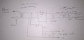
Bridge Rectifier not outputting calculated voltage

Tonyr1084

Joined Sep 24, 2015
9,744
If you put the fuse in the transformer's secondary circuit your would have to rely on a fuse wire inside the transformer in case there is a problem with the transformer. Granted it is a Signal transformer and they are very good but even with Signal transformers I used to put the fuse in the primary before the power switch.

@Tonyr1084 Good catch about the 100 uf cap.
Actually, a stereo amp I worked on a year or two ago had a shorted BR. It would blow the main fuse (7A) on the primary side. But there was another fuse on the secondary side - don't recall the amperage - but it had two fuses. To further test the circuit I used one of the blown fuses to connect a 110V lamp to. If the BR was shorted the light would light up instead of blowing the main fuse. Turned out that was exactly what happened. When I replaced the BR and powered up the lamp lit for a moment then settled down to a very dim glow. The BR was the problem. So I pulled it out of circuit and checked for shorts and sure enough, one leg was dead short. Fusing the primary side is also a good idea. Transformers rarely are the problem.
 

Reloadron

Joined Jan 15, 2015
7,891
Then all things considered I would use an opto coupler to just detect mains presence. Now measuring AC mains with an IoT or form of micro controller having an ADC (Analog to Digital) converter is a matter of taking a signal you have (120 VAC 60 Hz) and converting it to a signal you want (DC level proportional to AC level). They make some nice transducers for doing this. Since you really likely don't need a true RMS conversion I would guess Average RMS will be fine since you are looking at a sine wave. Just as an example in higher end there are transducers like this which typically are in the $100 USD price range. They afford outputs like 4 to 20 mA, 0 to 5.0 volts and 0 to 10 volts all proportional to their input voltage ranges. Most like this do require a 24 VDC power supply. Now, if that is a little too pricey I see plenty of little units like this off the boat from our little friends in China for a few USD each. A Google of "measuring ac mains voltage sensor" should yield a dozen Amazon and Ebay hits. They have everything on a nice little board using a mini transformer, diode bridge and scalable (adjustable) amplifier so you can adjust a DC out proportional to the AC line in. I doubt you can build something that cheap. :)

Ron
 

Thread Starter

vars90r

Joined Mar 24, 2020
30
Hello Ron,

Thank you for your reply. I did look into these transducers, specifically from Cr magnetics. I used one of them before. But here I don't have a 24Vdc power supply to power the transducer. Also, 120$ is not cheap. These can only sense the AC voltage but won't be able to power the device. I want to do both.

You could say I could buy both a transducer and converters from eBay or Amazon. But that's not very efficient. I will have two separate PCB boards for this application. That's why I'm going to this trouble of making a board that can sense and power the device and has an additional 4 rectifiers to just sense AC voltage.

The board is definitely cheaper.

Transformer 16$
Bridge rectifier 1$
Resistors combined 1$
PCB fabrication 15$ for 3 boards

The board can sense 6 AC voltages and power the device. To do this, I need 2 AC transducers and a Wall wart converter. transducers themselves will cost me 240$.

What I'm doing is not an impossible task. A lot of people have done it. Can you please let me know if there is something wrong with my circuit?

Thank you

Varun R

image-4-small.jpg
 
Last edited by a moderator:

Reloadron

Joined Jan 15, 2015
7,891
Whatever works for you. Commercial applications I don't see a few hundred dollars as expensive but I guess it is a matter of budget. I can shove a 24 VDC supply and AC transducer on a DIN rail and be done. I have not tried the inexpensive off the boar versions so can't speak for thwem but at about $2.50 each I may be tempted to try one.

Ron
 

Thread Starter

vars90r

Joined Mar 24, 2020
30
I understand your logic and I did a similar setup before with off the market products. Now the requirement is a little different. I need to monitor 6 AC voltages. A personalized board is a way to go if it's plausible in this case. Hence exploring this.

I even contacted many friends with whom I went to college to get a second opinion about this. I wouldn't try this hard if it wasn't worth the trouble.

Varun R
 

Reloadron

Joined Jan 15, 2015
7,891
If you want quick and simple then I would use something like this for a roll your own.

Mains to uC divider.png

The transformer can be a Triad Magnetics FS20-120-C2 or similar. They cost under $4.00 USD, the rest are common off the shelf parts. I guess if you plan to make little boards make R1 or R2 a 10 turn trimmer. Matter of fact as drawn Vout should be below or about VDC. Depending on your ADC adjust those values accordingly. Measure your actual AC in and your DC out, get a ratio and just write your code accordingly. I guess if you wanted you could use the CT of the transformer and a pair of diodes followed by a divider. I would keep my filter cap value low because you are working into an ADC which is likely a high input impedance and changes in mains will be harder to notice and take time to notice. Either way the whole thing should come in at under about $8.00 USD.

Ron
 

Thread Starter

vars90r

Joined Mar 24, 2020
30
Hello Ron,

That's should work. My question is Since ADC is of high impedance. Is the transformer necessary in this circuit? I simulated and hard wired the circuit you mentioned and I was able to read the voltage via ADC. If it is a safety issue, then I'll incorporate the transformer in the circuit. It's just that the board is getting bulkier. I have attached my schematic to this email. It's similar to what you suggested but without the transformer. The 30K resistor is rated at 2W. It dint burn when I ran this setup for 2 hours this Friday.


To power the device, I will use the following transformer. Its 16$ but it has a higher power rating of 25VA. So at 24V, it can provide 1A of current which is more than enough to power the device (0.3 to 0.4A). Also, Its safer, as we are pulling current from the main, this transformer acts as an isolation transformer.

https://www.digikey.com/product-detail/en/CL2-25-24/595-1890-ND/1118010/?itemSeq=321751876

Sorry for being a little redundant. I just want to know if Triad Magnetics FS20-120-C2 is necessary?

Thank you

Vaurn R
 

Attachments

Reloadron

Joined Jan 15, 2015
7,891
The transformer is in there because in good faith and forum rules, leaning towards forum rules, suggesting something like this sans a transformer would be greatly frowned upon. It does afford mains isolation which is looked upon favorably by those in power around here. :) Most ADCs I have worked with are multi channel be they single ended or differential input they use multiplexing (MUX). Each channel charges an input cap but all here nor there. The high input impedance is designed so as not to load the source.

Anyway is it necessary? Not really, it could be skirted. Do I suggest leaving it there? Yes. :) I do like the isolation though. Circuits like this have been used quite a bit since there is no shortage of people and applications where we want to measure mains using a uC like an Arduino, PICAXE or similar ADC channel. They are not exactly high precision designs but they work.

Your drawing would do fine too.

Ron
 

MrAl

Joined Jun 17, 2014
13,707
It is nice to see a transformer being used here. That is a lot safer. Just make sure it has the proper safety ratings.

I use a transformer too just to get the isolation but when measuring current i had to use a current shunt which has to connect inline with the power line. But i've gotten around that too by purchasing a clamp on ammeter. This meter has a transformer core that opens when you press the side button so you can clamp it on a fully insulated wire. It's the safest way to measure current in the power line. The one i got actually can measure surges too like when you switch something 'on'. That is hard to see with a regular current meter.
 

wfwardiii

Joined Mar 27, 2020
4
Hello

I'm trying to build a rectifier to power our IoT device which would be deployed in the field where there is no DC voltage available. I only have a 120VAC power supply.

I'm using bridge MDB6S to rectifier the AC voltage. Please refer to the attached picture for the circuit diagram. Then I'm using voltage divider to get 15V across the load resistor. The voltage divider is between 30K and 4.7K. The smoothing capacitor is connected across the 4.7K resistor.

https://www.digikey.com/product-detail/en/on-semiconductor/MDB6S/MDB6SFSCT-ND/3137112

When I don't connect anything to the load resistor (4.7K), I measure 15V by a multimeter.

But when I connect our device across the load resistor, it only reads 7.8V. The device pulls 0.3 to 0.4 A of current. Keeping this in mind, I now connected a 470uF capacitor across the load resistor (4.7K). It still does the same.

Any suggestions?

Mod eidt: Direct to mains / transformerless power supply schematic deleted - JohnInTX
Can I request that you draw a schematic of your circuit? I may be a able to help but I'm unclear as to what is being connected adn how it's hooked up.

I do agree in principle that connecting directly to the power main is potentially dangerous but there are times when you might make a judgement call to do it anyway.
 

wfwardiii

Joined Mar 27, 2020
4
Hello

I'm trying to build a rectifier to power our IoT device which would be deployed in the field where there is no DC voltage available. I only have a 120VAC power supply.

I'm using bridge MDB6S to rectifier the AC voltage. Please refer to the attached picture for the circuit diagram. Then I'm using voltage divider to get 15V across the load resistor. The voltage divider is between 30K and 4.7K. The smoothing capacitor is connected across the 4.7K resistor.

https://www.digikey.com/product-detail/en/on-semiconductor/MDB6S/MDB6SFSCT-ND/3137112

When I don't connect anything to the load resistor (4.7K), I measure 15V by a multimeter.

But when I connect our device across the load resistor, it only reads 7.8V. The device pulls 0.3 to 0.4 A of current. Keeping this in mind, I now connected a 470uF capacitor across the load resistor (4.7K). It still does the same.

Any suggestions?

Mod eidt: Direct to mains / transformerless power supply schematic deleted - JohnInTX
 

wfwardiii

Joined Mar 27, 2020
4
I have attached a sketch of the circuit that I would recommend. This will give your IOT device a steady power supply and it will also allow you to monitor the AC mains voltage with the Analog to Digital Converter on the IOT device. The voltage that the ADC reads will be porportional to the AC mains voltage but it will be lower and it will be DC. You may need to play with the value of the capacitor C1. If it's too big, it will smooth out the fluctuations in AC mains voltage and you will see a very slow response to a change in mains voltage. If it's too small the DC value will fluctuate 120 times per second and the ADC may give you erratic results. I'm thinking to start with maybe 5uf but I'm not sure if that's a good value. If you have a scope then you could make a determination, you don't want much ripple in the voltage but you do want to see a change quickly.

Make sure you put a heatsink of some kind on the voltage regulator because it will generate some heat. Also the mounting tab on the TO220 package is electrically connected to the common or ground terminal of the regulator so be conscious of that. You may also want to put a 1.5 - 4.7K resistor across the output of the regulator and possibly an LED so you see the power is on. R1 and R2 should be chosen to reduce the voltage to the range that you need for your ADC. You may also want to calibrate the voltage in software making the resistor values not so important.
 

Attachments

ebeowulf17

Joined Aug 12, 2014
3,307
I have attached a sketch of the circuit that I would recommend. This will give your IOT device a steady power supply and it will also allow you to monitor the AC mains voltage with the Analog to Digital Converter on the IOT device. The voltage that the ADC reads will be porportional to the AC mains voltage but it will be lower and it will be DC. You may need to play with the value of the capacitor C1. If it's too big, it will smooth out the fluctuations in AC mains voltage and you will see a very slow response to a change in mains voltage. If it's too small the DC value will fluctuate 120 times per second and the ADC may give you erratic results. I'm thinking to start with maybe 5uf but I'm not sure if that's a good value. If you have a scope then you could make a determination, you don't want much ripple in the voltage but you do want to see a change quickly.

Make sure you put a heatsink of some kind on the voltage regulator because it will generate some heat. Also the mounting tab on the TO220 package is electrically connected to the common or ground terminal of the regulator so be conscious of that. You may also want to put a 1.5 - 4.7K resistor across the output of the regulator and possibly an LED so you see the power is on. R1 and R2 should be chosen to reduce the voltage to the range that you need for your ADC. You may also want to calibrate the voltage in software making the resistor values not so important.
I don't think that works. The transformer secondary output is still AC, and neither side of it is directly ground referenced. For half of every cycle, the line that connects directly to ADC - input on your schematic will be almost 17V above IoT ground. The chip isn't gonna like that!

Maybe I'm misreading this - I'll probably try simulating it tomorrow to check my sanity, but that's what it looks like to me right now.

I have a hunch that you could take a split after the bridge rectifier and do the same voltage divider and cap and get a working solution, but I'd have to sketch it and/or simulate it to be sure. For now, it's past my bedtime!
 

DickCappels

Joined Aug 21, 2008
10,661
That is much better and almost works. I think the thread starter wants DC for his ADC, to get that, move R1 to the cathode of the rectifier.
 

wfwardiii

Joined Mar 27, 2020
4
I don't think that works. The transformer secondary output is still AC, and neither side of it is directly ground referenced. For half of every cycle, the line that connects directly to ADC - input on your schematic will be almost 17V above IoT ground. The chip isn't gonna like that!

Maybe I'm misreading this - I'll probably try simulating it tomorrow to check my sanity, but that's what it looks like to me right now.

I have a hunch that you could take a split after the bridge rectifier and do the same voltage divider and cap and get a working solution, but I'd have to sketch it and/or simulate it to be sure. For now, it's past my bedtime!
This written format is sometimes helpful but other times it's a barrier to communication. I don't know if I'm allowed to give you a phone number but if you call me we could talk about what you need and what will work or not work.

I'm assuming your IOT device needs a 12 volt supply to work. If it needs less, the voltage regulator chip can be changed to one that regulates a lower voltage. No matter whether your IOT draws full current (I think you said around .4 amps), or nothing the power supply voltage will be 12 volts.

As far as the sensing part of the circuit... I'm understanding that you're trying to measure the line voltage constantly. The transformer will isolate the 120 volt main so you don't have a shock hazard and the output of the transformer will vary with the line voltage. If you pull the current from the transformer before the bridge rectifier then you'll have a 12v rms voltage that varies with the line voltage. You can use one diode to rectify it and one capacitor to filter it and you'll have a DC voltage that is porportional to the AC line voltage. If I'm mis-understanding your objective or other information, let me know and I'll adjust accordingly.

I'm also going to draw the entire bridge circuit out on paper to make sure I'm not overlooking anything in the sensing circuit and I'll reply after I have done this.

Frank
 

Thread Starter

vars90r

Joined Mar 24, 2020
30
I"m sorry for not being clear. I'll address all the questions asked separately below.

There is a heater module where I need to measure AC voltage inside the module at 5 different places. The voltages at those 5 places vary according to a temperature controller inside the module. I need to design a board that can make this happen. I have a device that has 5 ADC's, 6 if you include the power line of the device.

The device can take voltage from 12V to 32V. At 12V the device consumes 0.3-0.4A. That's about 5W of power(Max). The average would be around 3.3W. I got this value when I connected the device to a DC power supply unit.

Also, the device power line is also an ADC. I'm not just powering the device, I'm also sensing the AC voltage to which the device is connected to(On the same line).


In the Diagram attached, I'm using the top part of the circuit to power the device and sense the voltage to which it's connected to. That's why I'm not using a voltage regulator.

Example: If the heater module is connected to 120VAC, the device gets 25VDC. If the heater module voltage drops to 60V, then the device gets around 12V. The device works and lets me know if the voltage ever drops. I'm sensing and powering the device at the same time.

To read AC voltages at 5 other places inside the heater module, I plan on using the bottom part of the circuit. Here R1 and R2 are 30K and 4.7K with a power rating of 2W. They won't burn until 250VAC (Simulated and tested on a PCB board) and the max current in the circuit will be 7.2mA. Also, the ADC's have high impedance. Hence I'm not using a stepdown transformer.

Example: If the voltage at a point is 120VAC, the ADC reads 15V. If it increases to 230V, then ADC reads 28V. I can sense 0-250VAC by ADC(0-32VDC).

Question:

I'm not using an isolation transformer in the bottom circuit (ADC part) considering the current is 7.2mA and it's going to high impedance (ADC). Is this safe? Ron already said it's fine.

Somebody brought it up now. Do I need to use a heat sink?

Mistake: In the diagram, the ADC line will be connected to the positive terminal of the 100uF smoothing capacitor. Sorry, my bad.

Varun R

Thank youUntitled-Mains-Measure-P39-small.jpg
Moderator's note: Please post diagrams in the correct orientation and use the minimum useful file size. (Above: rotated 19 kB version replacing 8 megapixel version in difficult orientation)
 
Last edited by a moderator:
Top