
Best method for converting PWM to analog signal?

crutschow

Joined Mar 14, 2008
38,609
My goal is to get a smooth sustained DC signal at 1.4V if I have a 50% duty cycle.
This is my circuit so far, where R5 & R7 reduce the PWM signal so it lies between the op amp's 0.3V - 2.5V rails.
The LM358 is not a rail-rail type op amp.
It has a maximum output of about 1.5V below the supply rail, so if you want 2.8V maximum output. the supply voltage should be 5V.

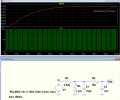
Below is the LTspice simulation a simple RCRC LP filter circuit that should do what you want:
You don't need an op amp since the Vset input has a high impedance.
From the data sheet:
"Leave floating, internal current source (typical 1.4µA) will pull up this pin to 4.5V"
This implies an input impedance of at least 3.2MΩ.

The output is 1.42Vdc for a 12V, 1kHz, 50% duty-cycle input, with a rise-time of about 22ms.
Of course the circuit will work well for any PWM frequency higher than that.
1648749420574.png
 

crutschow

Joined Mar 14, 2008
38,609
It doesn't utilize the full PWM scale though (0% = 0.3V; 50% = 1.4V; 100% = 2.5V).
How did you arrive at those voltages?
To get those values you would have to add some offset and non-linear gain.
PWM is linear so, for example, if 50% duty-cycle is 1.4V, then 0% would be 0V and 100% would be 2.8V.
Mind if I ask where you got your experience in filter design?
Mostly from reading about filters and simulating various designs in LTspice.
Spice is a great analog design tool for experimenting with various analog designs, including learning about the response of various filter types.
 

crutschow

Joined Mar 14, 2008
38,609
It is just 0.3V to 2.5V, so 1.1 is it's 50%. So I think I should be able to just play around with component values to modify the filter.
It requires more than just a change in component values, since you want a non-linear output from a linear input.
If you really need those points to correspond to 0%, 50%, and 100% PWM duty-cycle, then you will need to add an op amp at the filter output with some offset and non-linear gain.

Do you really need the output to exactly correspond to those input duty-cycles?
Otherwise just make 0.3V=12% duty-cycle, 1.25V=50% duty-cycle, and 2.5V=100% duty-cycle.
Or with 0.3V offset, 0.3V=0% duty-cycle, 1.4V=50% duty-cycle, and 2.5V=100% duty-cycle.
 
Top




