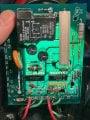
I cannot see the tracks on the PLS 2000 board clearly.
We want to see how E4 receives power. Trace E4 back and tell me to what component it is connected.
Or better still, post photos of both sides of the board with proper lighting so that we can see the tracks.
Without the sensor plugged in, but with power supply plugged in:
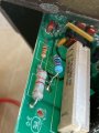
the resistor (“first stop”) has a resistance oL (I think that means error).
The voltage, with black DMM lead hooked up to white supply, is 102 VDC on the top side of resistor, and 2 mVDC (and dropping) on the bottom side.
should i run this with the Sensor plugged in… just realising that would make sense, eh ..
Without the sensor plugged in, but with power supply plugged in:
the resistor (“first stop”) has a resistance oL (I think that means error).
The voltage, with black DMM lead hooked up to white supply, is 102 VDC on the top side of resistor, and 2 mVDC (and dropping) on the bottom side.
should i run this with the Sensor plugged in… just realising that would make sense, eh ..
Just to be certain. Unplug power.
WITH POWER DISCONNECTED,
What was the range setting on the DMM resistance measurement?
Set it to 2M.
Touch the meter leads together and check that it reads 0.
Measure the resistance of that suspect resistor again.
If the reading is OL, replace the resistor. If you can see RED, BLACK, ORANGE, GOLD, it is a 20kΩ 5%.
It looks like a ½W resistor. Replace it with 20kΩ 1W resistor.
After you have replaced the resistor, plug in the sensor.
Measure the DC voltage at E4.
 Facebook
 Google
 GitHub
 Linkedin