Ah, ok, so the red and black wires go to the capacitive sensor and the rest of the circuit processes the sensor signal and does the switching. We now need to figure out how to bypass all that so you can do the switching manually. This shouldn’t be too hard.
Okay, I am going to take it apart and get you some pictures. I am just not there right now so it will take a little bit before I can provide it. Thanks!
This http://www.afiata.com/wp-content/up...tch-Circuit-Diagram-using-74HCT74-ZVNL110.jpg
isn't identical to your circuit but it gives you some idea of what the circuit is probably doing. The 74HCT14 is probably acting as the pulse generator. If you use a DMM and trace the large wires to the IC's you can see if they connect tot he 74HCT74 flip-flop. This could give you additional information about how to circumvent/replace the sensor.
You will probably be able to substitute in any simple capacitive-touch sensor.
Thanks for your continued support. I am now no longer at that house. Can we just let this thread sleep for a while until I get you the requested diagram @ wayneh? I feel that is what is needed, no?
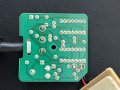
Wow, that's more complicated than I expected. Would it be hard to get a picture of the other side of that circuit board?
I think there's another level beneath the terminal area in the picture. Maybe there's more to see in there, a relay and and maybe a diagram.
Jingle Bells everyone. I’m back at my fathers house and back on the jacuzzi repair job.
First thing, I’ve taken apart the box and the Wiring Connection Diagram is simply the 6 terminal labels. But, for your viewing pleasure and support in assisting me with the reinstatement of bubble baths, I’ve added some more photos
Ideally I think I’d like to hook that pressure sensor input on the control box into a push button switch. It has three prongs, so I’m just not sure how I should be testing it to figure out how to hook it up.
Now that I’ve taken the control box out, I should be able to hook up power and a light pump (instead of motor) to test around what does what… I worry though that without the water level sensor hooked up that may have difficulty. Maybe I’ll just screw it all on a board temporarily to mess around.
any pointers or test suggestions happily received. Thanks !
These are common digital logic ICs and are readily available. They operate from 2-6VDC supplies.
The trimpot is for adjusting the sensitivity level of the sensor.
If you post a photo of the reverse side of the board we can reverse engineer the circuit.
You can test this circuit independent of the rest of the bathtub.
Firstly, use a DVM and measure the supply voltage coming into the board. (With the bottom view we will be able to tell you which wires are the power inputs)
With the board powered up (either from the system power or on a workbench), we will be able to test the proper operation of the circuit.
 Facebook
 Google
 GitHub
 Linkedin
 536.5 KB Views: 25