I’m back with a multimeter!
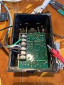
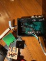
I have a lightbulb where the motor should be and an old extension cable for supply. Bench is dining table. Note, low water shutoff sensor is not connected.
I touched the green and black and got a voltage (VDC) of 0.700 V. I touch the sensor and nothing happens.
I did get the resistance conductivity beeping test working and figured out which pin is what color.
Set your DMM to 20V DC range.
While the sensor board power is on, connect the black lead (negative) of the DMM to the GND point shown.
Connect the red lead (positive) of the DMM to the testpoints.
#1 - expect to see about +12V (not critical)
#2 - expect to see +5V (this one is important)
Set your DMM to 20V DC range.
While the sensor board power is on, connect the black lead (negative) of the DMM to the GND point shown.
Connect the red lead (positive) of the DMM to the testpoints.
#1 - expect to see about +12V (not critical)
#2 - expect to see +5V (this one is important)
The Franklin Electric control unit PLS 2000 when uncovered has exposed components and solder joints at AC mains voltages.
If you are not capable of testing this unit safely then do not proceed.
Proceed at your own risk.
Disconnect the unit from power source.
Disconnect the motor connections.
Disconnect the sensor from the unit.
Connect only AC supply, black, white, green wires.
Set the DMM to 200V DC range.
With the unit power on, connect the DMM black lead to the GND point shown (SUPPLY WHITE).
With the DMM red lead, measure the DC voltage at the seven test points, one at a time.
Note that the board is covered with conformal coating. You will have to penetrate the coating in order to make proper contact.
WARNING
Some test points will be at 160V.
One slip of the hand or test probes and you can say bye-bye to the unit, or worse!
Basically, we are looking for a loss of low voltage power (about 10-15V DC expected).
Before I get started, I just want to confirm that I only have supply white and black hooked up to the control box. I won't have the ON/OFF sensor plugged in. Photo exemplifying test-point #1.
You did not show what is connected to the two brown wires to the board.
Hopefully you have this connected to a grounded (GREEN) power cord with the correct connection to AC NEUTRAL (WHITE) and AC LINE (BLACK).
For this test only, set your DMM to 750V AC.
With one test lead connected to EARTH (green wire),
confirm that the SUPPLY WHITE screw terminal is at 0V
confirm that the SUPPLY BLACK screw terminal is at 120V AC.
Reset your DMM to 200V DC and proceed with the DC voltage measurements.
Your extension cable may or may not be polarized.
Technically, for this measurement, it does not matter if the LINE and NEUTRAL are reversed.
For safety reasons, there is a difference. We would prefer that you were making a measurement with respect to NEUTRAL and not LINE.
Yes, if you can find a proper 3-conductor cord that would be preferred.
If you have a spare computer power cord that you can sacrifice that would be best. Cut off the end that fits into the back of the computer and throw that away. Strip back the BLACK, WHITE and GREEN wires of the cable.
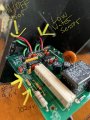
Looks like you have a blown component on that board.
Disconnect the board from AC power.
Set your DMM to diode setting.
Measure across the diode, one at a time, once with red to bar marking on the diode, again with the leads reversed (black on the bar).
What is the capacitance and voltage markings on the capacitor?
Diode that is pictured virtually with “NG” has 0.500 V when in diode mode with black on top and red on bottom. DMM reads “OL” when red on top and black on bottom.
The horizontally positioned diode reads “OL” with red on left, but again 0.500 V (or just under) when red on right.
With AC power cable connected, set the DMM to 750V AC.
The DMM black probe is connected to SUPPLY WHITE as shown.
Test points
#1 - 120V AC expected
#2 - 120V AC expected
#3 - 120V AC expected
If you don't get 120V on #2 and #3, unsolder the capacitor and lets see the PCB traces that were hidden underneath the capacitor.
I would also like to see a photo of the markings on the capacitor. (Disconnect AC power, of course!)
If the capacitor is found to be faulty, they installed the wrong capacitor!
Also it would be nice to see the markings on the great big power resistor that is about 2" long (if the markings are visible on the sides, usually its on the top which is against the PCB).
It seems that my supply cable was faulty (the blue/green corrosion apparently does make a difference). I noticed that the voltage on the red probe when measuring the black supply was reading 10V and, when comparing with what I got out of the wall, there clearly was an issue.
I've replaced the power line with a new computer power cable and rerun the tests. The figures in post #52 are incorrect. These are the new values:
1) 53.1 V
2) 53.1 V
3) 100.8 V
4) fluctuating (and dropping slowly as I test) from 4 to 1.8 mV
5) 114.1 V
6) 100.5 V
7) 9.6 V
I've also adjusted these values in post #52. I apologize for this mistake!
Low water sensor (not plugged in)
E1) 9.6V
E2) 0 (nothing plugged in)
E3) jumping all over the place
On/Off switch
E4) 0.744 V
E5) 0 (I also tried squeezing the touchpad on the sensor and it didn’t do anything.. not sure if that activates it)
E6) 0.744 V
Does this help? What’s next ? I feel like we are getting somewhere !
 Facebook
 Google
 GitHub
 Linkedin