
Austin's Transistor Dossier: An Analysis of Transistor Design
- Thread starter ELECTRONERD
- Start date
Scroll to continue with content
Well, unfortunately this is not true. Re helps a lot.But the VBE voltage still remains: Vth * ln (IC / Is).
So, its DC operating point's dependence on the temperature remained the same.
The Vbe decreases as temperature s -2mV/K, β increases 1%/K and Iceo doubles when temperature increase of 7.5K
So if temperature rise Δ30°C then β will increase by 30%.
Ico will be 2^(30/7.5)=2^4= 16 times larger.
And for example this amplifier:

And If we increase temperature from 27°C to 77°C
ΔT=50°C
We get:

ΔIc≈1mA
ΔVc≈-1V
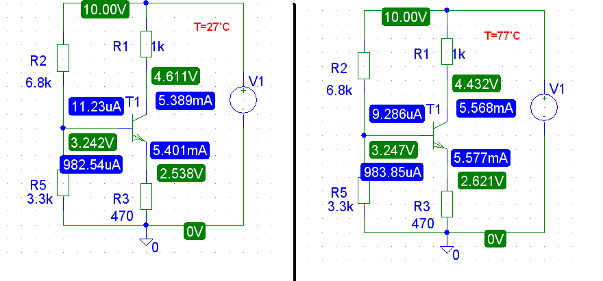
And now we add Re=470Ω resistor and voltage divider.

And again we increase temperature from 27°C to 77°C
ΔT=50°C

ΔIc=0.767mA
ΔVc=0.767V
And we get further improvement if we use Re+ voltage divider
Ups... yes,you are absolutely right. I forgot about that.Jony130, you have apparently ignored the fact that the impedance looking into the collector is not simply Hoe, but is substantially higher due to the feedback provided by the external emitter resistance. Have a look here for an analysis.
Oh i see, thank you very very much! ")
What are the reasons therefore that we wouldnt want to pick a very large RE?
(Assuming that its coupled with a capacitor and therefore only affects the "DC circuit").
(For example, we decrease the max. output voltage swing by increasing RE).
What are the reasons therefore that we wouldnt want to pick a very large RE?
(Assuming that its coupled with a capacitor and therefore only affects the "DC circuit").
(For example, we decrease the max. output voltage swing by increasing RE).
Wow, lots of good information! It is interesting to see how temperature affects a given transistor circuit.
Austin
Austin
Wow, lots of good information! It is interesting to see how temperature affects a given transistor circuit.
Austin
You got that right..
I was just working on a class A stage, trying to put 5v pk. across 470 ohm load. using 22v. for VCC. so as to be able to get the signal swing.
Using a RC = to the load meant I had to increase the gain double,
so with a 470 ohm collector resistor, I used a 16 ohm emitter resistor, which gives me a DC gain of around 30, but an AC gain of around 15.
Well, when I went to verify the DC bias at the collector, I had my 11v. at the collector, but as the transistor kept heating up the voltage kept dropping and dropping, until it rested at around 9.4v.
I checked the base voltage and it was at the right value, calculated, so no base current loading, but rather the emitter resistor was too small and did not have enough negative feedback to compensate for the drifting current.
So I raised the emitter resistor to 47 ohms, and now the collector DC bias voltage, remains stiff at around 10.8v.
So what was happening was there was not an excessive current to cause overheating, but rather the small change in temperature that normally happens at that current value, had a greater affect on the collector voltage because the emitter resistor was too small to be able counteract the change in emitter current.
Once the resistor was larger the emitter current became more stable.
Due to negative feedback.
So instead of a Av. of 10 I had to design 3 stages with a gain of 5 each.
Since I don't know how Ron derived the correct value for R5, I am going to stay put with just a single Re resistor.
As for calculating the value of the cap across the emitter resistor, the equation below is necessary:
\(X_c=\frac{1}{2 \pi f C\)
What would be an adequate reactance for Xc?
Austin
As for calculating the value of the cap across the emitter resistor, the equation below is necessary:
\(X_c=\frac{1}{2 \pi f C\)
What would be an adequate reactance for Xc?
Austin
That resistor is the value equal to around (R1 / Av.) AC gain not DC gain.Since I don't know how Ron derived the correct value for R5, I am going to stay put with just a single Re resistor.
As for calculating the value of the cap across the emitter resistor, the equation below is necessary:
\(X_c=\frac{1}{2 \pi f C\)
What would be an adequate reactance for Xc?
Austin
DC gain is R1 / R2) AC signal gain is R1 / R5..
I see so Xc=(R1 / Av) - for AC gain.That resistor is the value equal to around (R1 / Av.) AC gain not DC gain.
DC gain is R1 / R2) AC signal gain is R1 / R5..
Since you say that AC signal gain is R1 / R5, I've often seen just the capacitor and no resistor; but Ron does have that resistor. Is there a specific advantage as to why I should have it?
Austin
You want some AC feedback too, if it were plain cap. then input impedance would be VERY low, to signal source, with some AC feedback it allows some better high frequency response as well.
As well as kepping a stiff gain so as to not be transistor parameter dependant.
You should always have some neg. feedback. with transistor amps.
As well as kepping a stiff gain so as to not be transistor parameter dependant.
You should always have some neg. feedback. with transistor amps.
So that resistor in series with the cap ensures AC feedback with a higher input impedance?You want some AC feedback too, if it were plain cap. then input impedance would be VERY low, to signal source, with some AC feedback it allows some better high frequency response as well.
As well as kepping a stiff gain so as to not be transistor parameter dependant.
Austin
So that resistor in series with the cap ensures AC feedback with a higher input impedance?
Austin
Yes it does...
My design proceeded as follows:Since I don't know how Ron derived the correct value for R5, I am going to stay put with just a single Re resistor.
As for calculating the value of the cap across the emitter resistor, the equation below is necessary:
\(X_c=\frac{1}{2 \pi f C\)
What would be an adequate reactance for Xc?
Austin
1. I arbitrarily decided to set Ic≈Ie≈1mA.
2. I chose Ve≈1V, which is large enough to make the nominal ΔVbe≈2mV/°C relatively insignificant, but small enough that the signal swing at the collector can be fairly large. This requires that R2=1k.
3. I chose Vcc=20V for large signal swing, and Vc≈10V so that limiting on positive and negative peaks will occur at approximately the same input voltage amplitude. This requires that R2=10k.
4. I chose the bias network so that I(R3) and I(R4)≈Ic/10, for stability with changes in β due to temperature and/or individual device characteristics.
5. In order to get a gain of 100, the total emitter resistance re+(R2||R5) needs to be approximately equal to R1/100 (remember re≈26Ω @ Ie=1mA). This assumes that the impedance of C2<<R5 at midband. The calculated value of R5 is 82Ω. I chose the next lowest standard value (75Ω) because I knew that there would be a little gain loss due to β and Hoe.
6. I arbitrarily chose F(-3dB)≈20Hz. For C2, F(-3dB)=1/(C2*2*∏*(re||R1)+R5). 100μF is the next highest standard value.
7. I have to admit I sorta pulled the value of C1=1μF out of a hat, knowing from experience that I would get about the same -3dB point for the input coupling. It might be better if C1 a little larger, in order to get the 20Hz cutoff point.
Note that I used a lot of approximations here. The precise calculations are good for understanding where the approximations can be made. Component tolerances are such that the approximations I made are justified, and make life a lot simpler.
The whole process of designng, drawing, and simulating the circuit took a lot less time than it did for me to write this up.
Thanks Ron, glad to have that post. I did notice the approximations, but I'll do as you advised and begin with the precise calculations.My design proceeded as follows:
1. I arbitrarily decided to set Ic≈Ie≈1mA.
2. I chose Ve≈1V, which is large enough to make the nominal ΔVbe≈2mV/°C relatively insignificant, but small enough that the signal swing at the collector can be fairly large. This requires that R2=1k.
3. I chose Vcc=20V for large signal swing, and Vc≈10V so that limiting on positive and negative peaks will occur at approximately the same input voltage amplitude. This requires that R2=10k.
4. I chose the bias network so that I(R3) and I(R4)≈Ic/10, for stability with changes in β due to temperature and/or individual device characteristics.
5. In order to get a gain of 100, the total emitter resistance re+(R2||R5) needs to be approximately equal to R1/100 (remember re≈26Ω @ Ie=1mA). This assumes that the impedance of C2<<R5 at midband. The calculated value of R5 is 82Ω. I chose the next lowest standard value (75Ω) because I knew that there would be a little gain loss due to β and Hoe.
6. I arbitrarily chose F(-3dB)≈20Hz. For C2, F(-3dB)=1/(C2*2*∏*(re||R1)+R5). 100μF is the next highest standard value.
7. I have to admit I sorta pulled the value of C1=1μF out of a hat, knowing from experience that I would get about the same -3dB point for the input coupling. It might be better if C1 a little larger, in order to get the 20Hz cutoff point.
Note that I used a lot of approximations here. The precise calculations are good for understanding where the approximations can be made. Component tolerances are such that the approximations I made are justified, and make life a lot simpler.
The whole process of designng, drawing, and simulating the circuit took a lot less time than it did for me to write this up.
I'll be working on Attempt #3 soon everyone!
Austin
Thanks loosewire. Once I ideally master Class-A amps, I'll post another Attempt #X that will give a practical approach on how to bias for Class-A amps for everyone's benefit.Are you being advised about putting your work out that can be copied
anywhere in the world. I admire your Intelligence real or seeking to be
a great contributor.
Austin
Am I to simply measure the typical input impedance of the microphone and then subtract that from what impedance I need? Then I can use the difference for that resistor value?Yes it does...
Austin
It is difficult to measure the impedance of an electret mic because it has a FET transistor inside. Its impedance is about 3.3k ohms and it is powered from a 10k ohms resistor. Then the preamp input impedance should be 15k ohms or more to avoid the mic output from being loaded down.Am I to simply measure the typical input impedance of the microphone and then subtract that from what impedance I need? Then I can use the difference for that resistor value?
Austin
But your transistor will have an input impedance of only 4k ohms which is too low. Don't add a series resistor to increase the input impedance because it will just reduce the level.
Hi Audioguru,It is difficult to measure the impedance of an electret mic because it has a FET transistor inside. Its impedance is about 3.3k ohms and it is powered from a 10k ohms resistor. Then the preamp input impedance should be 15k ohms or more to avoid the mic output from being loaded down.
But your transistor will have an input impedance of only 4k ohms which is too low. Don't add a series resistor to increase the input impedance because it will just reduce the level.
Thanks for the post, I will try and focus on changing the actual amp impedance if I can.
Austin
Electronerd
do you have any passive input devices at all.
If you can master designing a audio amp, using passive devices, first, than you'll have a better understanding of what is needed to couple a active device to an amp stage.
That's why I use two speakers, for input and output.
That gives enough design challenge in it's self.
Last edited:
You May Also Like
-

New U-blox Modules Support Simultaneous Positioning and Communications
by Aaron Carman
-

Microchip Shows Off Qi 2.0 Wireless Power Transmitter Reference Design
by Aaron Carman
-

Altera Infuses AI Into New Mid-Range FPGAs
by Dale Wilson
-

SemiQ Introduces New High-Frequency, High-Power SiC MOSFET Modules
by Duane Benson