Your divider current is 15V/38k= 1.9mA, not 500uA.
Calculate the base current.
The collector resistor has 6V across 625 ohms so the collector current is 9.6mA.
The hFE for the 2N3904 transistor at 9.6mA is from 100 to 300.
Then the base current is from 32uA to 96uA.
Great job, you stayed with it, you didn't give up, but kept on plugging away,
You have designed a very well biased circuit, the gain of the circuit without distortion, is around the value of your, RC / RE ratio, and your divider has the voltage and currents you calculated for, so your design swo far shows successful.
Since you designed it for a Av. of 3, then to you it is a significant amplification, since it meets the requirements you designed it for.
As long as it has met your requirements it is a total success.
That can't possibly be true. According to the AAC e-book, to convert Rb and Vb to a voltage divider you do the following: \(6320 \frac{15V}{3.16V} = 30k\) So \(R_1=30k\), and to find \(R_2\) you do the following: \((\frac{1}{6.32k}-\frac{1}{30k})^-^1=8k\)
Calculate the base current.
The collector resistor has 6V across 625 ohms so the collector current is 9.6mA.
The hFE for the 2N3904 transistor at 9.6mA is from 100 to 300.
Then the base current is from 32uA to 96uA.
I'm not using the 2N3904. Go back to my previous posts and you'll see that I'm using the BC547B transistor. Since I couldn't find it on the simulation program, I used the 2N3904 to still get a general idea.
Great job, you stayed with it, you didn't give up, but kept on plugging away,
You have designed a very well biased circuit, the gain of the circuit without distortion, is around the value of your, RC / RE ratio, and your divider has the voltage and currents you calculated for, so your design swo far shows successful.
Since you designed it for a Av. of 3, then to you it is a significant amplification, since it meets the requirements you designed it for.
As long as it has met your requirements it is a total success.
Hey thanks hobbyist! I really appreciate the encouragement and all the help from everyone! My next step is to try and suck all the gain and Av I can out of this transistor so I can make it as efficient as possible. So for Attempt #3, I'm going to try and increase the gain and also Av. Then I'll try to add multiple stages, which I know your good at; so I'm sure I'll be needing some help.
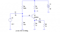
I assembled the circuit from Attempt #2; the schematic is shown in the attachment. The results were excellent! I was very suprised at the volume when I listened to myself speak via the ceramic earphone!
I was reviewing the "quiescent" point of a Class-A amp in the AAC e-book and realized that the base current should be somewhere in the middle of the graph. I believe they found the average in their listed graph, so I did (400μA x 50μA)/2 = 250μA. Unfortunately, this will make Ic=60mA which in turn will make the impedance lower; therefore reducing power output. What I'm going to do is keep on moving Ib up according to the graph (Pg. 2 of datasheet, Figure 1). For Attempt #2 I did 50μA and next I'll do 100μA and so on. By doing this I will examine the changes of conditions for the amplifier.
if you do, you can really get a good understanding of transistor amp design, now that you learned how to bias it into class A,
by using a function generator, and oscope, you can learn how the input impedances affect the waveform of the input signal and how to compensate for that, as well as you can see how the voltage gain works as you vary the amplitude and watch for clipping on the output.
A microphone input is good, but a signal generator will help you establish a better understanding of how the amp works.
ELECTRONERD, you should be aware that the ceramic earphone you're using for a load has a very much higher impedance than the little speaker that was used in another thread.
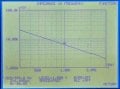
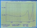
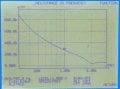
I've measured the impedance of a ceramic earphone I had laying around, and I've attached images showing the measurements of various properties versus frequency over a range of 300 Hz to 3 kHz, approximately the voice band..
The earphone is mainly a capacitive load. It looks like a capacitor of 25 nF with a parallel loss resistance that decreases with frequency. There is a resonance around 2 kHz.
The impedance varies from about 20 kilohms at 300 Hz to about 2 kilohms at 3000 Hz. It would be fair to take the average impedance to be about 6.5 kilohms over the band.
This means that you can use a much larger Rc than you have so far. Given the low output level of your microphone, you should be able to have a gain approaching 100.
if you do, you can really get a good understanding of transistor amp design, now that you learned how to bias it into class A,
by using a function generator, and oscope, you can learn how the input impedances affect the waveform of the input signal and how to compensate for that, as well as you can see how the voltage gain works as you vary the amplitude and watch for clipping on the output.
A microphone input is good, but a signal generator will help you establish a better understanding of how the amp works.
Yes I do indeed have an o'scope and function generator, I'll have to start using them. I like using the actual equipment much better than the simulation programs anyway, so thanks for the advice.
ELECTRONERD, you should be aware that the ceramic earphone you're using for a load has a very much higher impedance than the little speaker that was used in another thread.
I've measured the impedance of a ceramic earphone I had laying around, and I've attached images showing the measurements of various properties versus frequency over a range of 300 Hz to 3 kHz, approximately the voice band..
The earphone is mainly a capacitive load. It looks like a capacitor of 25 nF with a parallel loss resistance that decreases with frequency. There is a resonance around 2 kHz.
The impedance varies from about 20 kilohms at 300 Hz to about 2 kilohms at 3000 Hz. It would be fair to take the average impedance to be about 6.5 kilohms over the band.
This means that you can use a much larger Rc than you have so far. Given the low output level of your microphone, you should be able to have a gain approaching 100.
Thanks The Electrician, but in the "Static Characteristics" graph, the gain is always 240 (Ic/Ib). I'll lower the collector current and have a gain of 100. I'll let everyone know how it goes. Now that you mentioned it, impedance is a primary facet I should think about at this point.
Thanks The Electrician, but in the "Static Characteristics" graph, the gain is always 240 (Ic/Ib). I'll lower the collector current and have a gain of 100. I'll let everyone know how it goes. Now that you mentioned it, impedance is a primary facet I should think about at this point.
I didn't follow the advice I gave in another thread about being more specific when using the word "gain". I was referring to voltage gain, not current gain.
You should be able to design a stage with much higher voltage gain than 3; I don't see why you shouldn't be able to have a voltage gain approaching 100.
I never expected it possible to have a voltage gain approaching 100, this is very exciting! Increasing Rc will reduce Ic thus reducing the hFE. But, the good news is that it will increase Av. Would I have to reduce the hFE in order to increase Av? If there is no other option I suppose it would be nice to have each of the gains balanced (hFE=100 and Av=100). Another addition that would increase the voltage gain would be a capacitor in parallel with Re. I will calculate the capacitance based on the average voice frequency.
One thing I'm curious about is in the "Static Characteristics" graph (Pg. 2, figure 1), they only list Ib, Ic, and Vce. They don't provide the emitter current. However, a common rule would be Ic≈Ie. But what If I didn't do that and increased the current at the emitter (thus lowering the resistance and increasing Av)? Would the transistor become unstable?
A hearing aid is an excellent project! It would especially be miniscule if I used SMT components.
I didn't follow the advice I gave in another thread about being more specific when using the word "gain". I was referring to voltage gain, not current gain.
You should be able to design a stage with much higher voltage gain than 3; I don't see why you shouldn't be able to have a voltage gain approaching 100.
In Ron schematics Re is R2.
And R2 helps to determine the bias point, makes the operating point less dependent form temperature change.
R5 was added in order to set voltage gain equal 100V/V

 Facebook
 Google
 GitHub
 Linkedin