Audio Preamp Circuit for a Microcontroller

sparky 1

Joined Nov 3, 2018
1,218
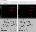
I will conclude the 3.3V 2N3904 preamp with a circuit emphasis on current derived by simulator. In this circuit I used a mA meter inserted between Vcc and the resistor of the collector. I calculated a gain of 3 but having the goal of 10 mA current draw. The meter was useful in aiming for 10mA. I adjusted the bias network for lowest total harmonic distortion. 0 .016% THD Sinad 76dB for an R_load of 2k. I did see the small offset in the function generator having less significance as the THD lowered and the scope revealed the offset diminish. Regarding the response. It is weak as the frequency gets real low but is great above 1Khz which is to be expected. Adjusting Rload can further lower the THD. Circuit might be worth saving this image for later simulation. I will try to post a working circuit later on the thread How to build your own function generator by Cezar Chirila
because I can benefit from his work and his code. I think the moderators prefer new thread so the introductory will need to refer back to Chirila. Maybe I could put an emphasis on making the most of arduino for cheap audio range generator instrumentation. Audio is one of the aspects of electronics that I waited to later in life and it's hard to remember everything about or all about circuits. I purchased a Freenove Uno for that application.
low distortion audio preamp 3.3V.JPG
 
Last edited:

Audioguru again

Joined Oct 21, 2019
6,826
It seems that your last circuit was not calculated but instead used random parts values. It has signal loss, not gain.
It reduces audio frequencies below about 2kHz since the capacitor values are much too low. It is distorted.
I don't know why you want the load to be as low as only 2k ohms and power supply to be only 3.3V.

Even though I used your low load resistance and low supply voltage, I calculated a few parts values to make it have a gain that is 23 time more than yours, much less distortion and much better bass response.
 

Attachments

sparky 1

Joined Nov 3, 2018
1,218
I agree the input and output can be adjusted. I used 20mV with the voltage amp and 20mV for this latest current amp. Later I will run the distortion analysis using your values. Probably correct to use 40 mV because a power supply ripple of 1mV. The TI application note says that 24db filter reduces .02 down to .002 THD so depending on the noise rejection the the op amp might obtain .003 percent THD
 

sparky 1

Joined Nov 3, 2018
1,218
Audioguru, I actually did calculations mine is .016% with gain of 3 so a maximum gain input for many science sensor experiments in audio.
There is a difference in application Your THD is 0.8% the gain is 22.5 There is a nice improvement in power from 1 Hz to 1kHz range. maybe the capacitors value is better, it is a good to go music audio amp for output. I will save a copy for later reference.

I think we have given circuit examples now the experimenter can choose an operating point for 2N3904 3.3V that works for their application.
Thanks for sharing your ltspice circuit for audio. For me it's time to move the signal above the noise floor. Now there is enough current for experimenter level. Going to the LM5532 now
 

Audioguru again

Joined Oct 21, 2019
6,826
A transistor part number has a wide range of hFE but a simulator picks only one. You must calculate your transistor design at a minimum hFE then at a maximum hFE to make it work with any passing transistor, usually by using DC negative feedback.

An old 5532 is an NE5532, not an LM5532. You can buy fake LM5532 ICs on ebay and Alexpress but if you look closely they are marked NE5532 because they do not know what their sellers are selling and they still might be fake ones.
An NE5532A has guaranteed low noise for audio.
 

sparky 1

Joined Nov 3, 2018
1,218
TI NE5532P is a p-dip for machines that use tubes of 50 package regular. it is not the SA5532P that has a higher temperature range and it is not a NE5532A so it does'nt meet the higher temperature criteria. While both A and P will pass the minimum nV/Square root Hz the A will have a maximum that exceeds the P. yes the NE5532A type will usually perform slightly better. A replacement being OPA2228 reputation of having a clean sound. Also the object of adding more sim examples so logical to migrate from the uA741 having plenty of applications. You wont need a big sack of OPA2228's
 
Last edited:

Audioguru again

Joined Oct 21, 2019
6,826
Digikey has thousands of NE5532A in stock today in surface mount and DIP packages made by ON Semi and Texas Instruments.
P is a DIP package and has nothing to do with noise but an A has guaranteed low noise.
NE are for home use and SA are used in aircraft or military extreme ambient temperatures.

The lousy old 741 opamp design is 52 years old and its spec's are awful. The NE5532 is also fairly old but it performs much better.
Nobody can hear a difference between an NE5532A and an OPA2228. The OPA2228 is made for audiophools with lots on money to blow away. An audiophool boasts to his friends that his distortion is only 0.00005%.
 
Top