You still haven't answered my question in post #36. Before moving on to the display, is the arduino/PWM part working or does the arduino still constantly reset? If it is working, what did you do to fix it?
You still haven't answered my question in post #36. Before moving on to the display, is the arduino/PWM part working or does the arduino still constantly reset? If it is working, what did you do to fix it?
What frequency are you using on your inductor, if you can hear it, it must be very low. Have you de-activated the divide by 8 fuse on the microcontroller?
1) That mosfet controller (IR2106s) relies on a charge pump to boost the Vgs of the top mosfet. I don't believe it will work at 100%. That is, it needs to have some off time for the capacitor to charge.
2) Your schematic has neither a coil nor LCD display in it. Where are they attached?
3) What type of display are yo using? Is the display driver a Hitachi HD44780 or compatible device?
4) What is your interface with the display?
5) Show your code for initialization of the display.
1) That mosfet controller (IR2106s) relies on a charge pump to boost the Vgs of the top mosfet. I don't believe it will work at 100%. That is, it needs to have some off time for the capacitor to charge.
2) Your schematic has neither a coil nor LCD display in it. Where are they attached?
3) What type of display are yo using? Is the display driver a Hitachi HD44780 or compatible device?
4) What is your interface with the display?
5) Show your code for initialization of the display.
1. i did almost hundred percent. since i limit the duty cycle at 157 (160 in full)
2. i jsut use i2c lcd. i did some test in lcd and it is working fine with zero duty cycle.
3. th code for lcd is in the first post of this thread.
1) That mosfet controller (IR2106s) relies on a charge pump to boost the Vgs of the top mosfet. I don't believe it will work at 100%. That is, it needs to have some off time for the capacitor to charge.
2) Your schematic has neither a coil nor LCD display in it. Where are they attached?
3) What type of display are yo using? Is the display driver a Hitachi HD44780 or compatible device?
4) What is your interface with the display?
5) Show your code for initialization of the display.
1 - This is not so, the charge pump capacitor charges to 12V when Q4 is on, so will be @ Q5 source voltage +12V when Q4 is off... so that is fine.
2 - The coil connections can be inferred from the PCB..
1 - This is not so, the charge pump capacitor charges to 12V when Q4 is on, so will be @ Q5 source voltage +12V when Q4 is off... so that is fine.
2 - The coil connections can be inferred from the PCB..
What value is your inductor by the way?
What happens if you use 2% on and 98% off ? As for a buck you need more off time than on anyhow.
For the LCD problem it is most likely to do with high frequency ringing which will occur between pulses as Q4 and D5 will take a short time to activate, during which you will see large amplitude oscillations at the junction of Q4 & Q5.
You could try adding a "snubber" across D5, and replace it with a higher speed Schottky
This: https://www.edn.com/Pdf/ViewPdf?contentItemId=4441467
Has a bit more information of the problem (though just one I quickly found on the web - there is lots of stuff available on this).
This interference might be enough to reset your micro-controller. But there is also the possibility you get "shoot through" that is your FETs do not switch quite quick enough, and there is a brief period where both are on at the same time. The easiest way to trouble shoot this might be to simply use a loop with delays to see if it has an effect rather than fiddling with the timer eg...
Q5 on
delay 5us
Q5 off
delay 1us .. or do something else, like switch on another port or LED etc.. just to waste some time.
Q4 on..
delay 30us
Q4 off
delay 1us .. or do something else, like switch on another port or LED etc.. just to waste some time....
Do you have an oscilloscope?
Ideally you want to look at the gate signals, and the junction of Q4 & Q5 so you can see what is happening.. making sure that the Q5 supply voltage pulse dies away before Q4 switches on hard and seeing how bad the ringing actually is.
Your Arduino is resetting because you are drawing too much current, and voltage is collapsing- that's how Ohm's Law works. The higher duty cycle, the more current you draw with PWM. Why don't you try 50%/50% for PWM, or try 10%/90%. At some point, the problem should stop regarding reset, and that will let you know where that threshold is. Make changes accordingly.
If your scope has single sweep mode set it up for Vdd + 1V, then Vss - 1V,
and see if you get triggered. Look at MCU supply pins This is a way of detecting
you could have an I/O pin getting a pulse outside its allowable logic level which
can inject charge into substrate, if that happens all bets are off as to what the
MCU does and operates.
Also not all caps are equal in their ability to provide low ESR to noise -
Lastly grounding and minimizing stray L is everything. High and low side fets
need L clamp diodes, either internal or external. Use split ground for high current
path and MCU and join them at board edge where power comes into board.
hi i have an update about my diy mppt but having a problem. my first guess is that the battery has a high resistance. may be the battery is not anymore since it is stock for almost 3 years and not used by then. if not what would be the possible problem? i cant afford to buy new battery as of now. jsut ignore the pwm duty cycle display since i am not finish programming that part. as you can see the battery voltage rise up more than its maximum voltage of the battery.may be you could help me figure out the problem.
hi
i am trying to build an mppt charger using arduino nano and right now i am having a problem with my mppt.
i already test all the components and working fine. the current sensor is okay and also the voltage sensor is okay.
but when the mppt start pwm then the arduino keeps resetting every seconds.
Code:
#include <LiquidCrystal_PCF8574.h>
#include <Wire.h>
LiquidCrystal_PCF8574 lcd(0x27); // set the LCD address to 0x27 for a 16 chars and 2 line display
int show = -1;

uint16_t PWM_MIN = 96;
uint16_t PWM_MAX = 150;
uint16_t PWM_DUTY = 120;
#define PWM_INC 1 //the value the increment to the pwm value for the ppt algorithm
#define AVG_NUM 20
#define SOL_AMPS_PIN A0
#define SOL_VOLTS_PIN A3
#define BAT_AMPS_PIN A1
#define BAT_VOLTS_PIN A2

#define SENSOR_SCALE 0.05 // 50mv per amper

double VOLTAGE_DIVIDER = 0.04912836767; //(r2/(r1+r2))
double VOLTAGE_REFERENCE = 4.096;       //external Vref
double SOL_AMPS = 0.0;
double SOL_VOLTS = 0.0;
double BAT_AMPS = 0.0;
double BAT_VOLTS = 0.0;
double SOL_WATTS = 0.0;
double OLD_SOL_WATTS = 0.0;
double OLD_SOL_VOLT = 0.0;

double OFFSET_SOLAR = 0.0;
double OFFSET_BATTERY = 0.0;
void setup() {
  // put your setup code here, to run once:
  TCCR1A = 0xB2;
  TCCR1B = 0x11;
  ICR1 = 160;
  DDRB = 0x06;
  OCR1A = 0; // pin 9
  OCR1B = 0; // pin 10
  int error;
  analogReference(EXTERNAL);
  analogRead(A0);
  analogRead(A1);
  analogRead(A2);
  analogRead(A3);
  Serial.begin(115200);

  Serial.println("Dose: check for LCD");
  Wire.begin();
  Wire.beginTransmission(0x27);
  error = Wire.endTransmission();
  Serial.print("Error: ");
  Serial.print(error);
  if (error == 0) {
    Serial.println(": LCD found.");
    show = 0;
    lcd.begin(16, 2); // initialize the lcd
  } else {
    Serial.println(": LCD not found.");
  }
  lcd.setBacklight(255);


  OFFSET_SOLAR = read_adc(SOL_AMPS_PIN);
  OFFSET_BATTERY = read_adc(BAT_VOLTS_PIN);
}

void loop() {
  read_data();
  if (SOL_WATTS > OLD_SOL_WATTS) {
    if (SOL_VOLTS > OLD_SOL_VOLT)
    {
      PWM_DUTY += PWM_INC;
    }
    else
    {
      PWM_DUTY -= PWM_INC;
    }
  }
  else {
    if (SOL_VOLTS > OLD_SOL_VOLT)
    {
      PWM_DUTY -= PWM_INC;
    }
    else
    {
      PWM_DUTY += PWM_INC;
    }
  }

  if (PWM_DUTY < PWM_MIN) {
    PWM_DUTY = 96;
  }
  if (PWM_DUTY > PWM_MAX) {
    PWM_DUTY = 150;
  }
  OLD_SOL_VOLT = SOL_VOLTS;
  OLD_SOL_WATTS = SOL_WATTS; // load old_watts with current watts value for next time

  OCR1A = PWM_DUTY - 10;
  OCR1B = PWM_DUTY;

  delay(100);
  lcd.setCursor(0, 0);
  lcd.print(SOL_WATTS);

  lcd.setCursor(8, 0);
  lcd.print(SOL_VOLTS);

  lcd.setCursor(0, 1);
  lcd.print(BAT_VOLTS);

  lcd.setCursor(8, 1);
  lcd.print(SOL_AMPS);

}


void read_data(void)
{
  int temp_sol_amps = read_adc(SOL_AMPS_PIN);
  int temp_sol_offset = temp_sol_amps - OFFSET_SOLAR;
  if (temp_sol_offset < 0)
  {
    temp_sol_offset = 0;
  }

  int temp_bat_amps = read_adc(BAT_AMPS_PIN);
  int temp_bat_offset = temp_bat_amps - OFFSET_BATTERY;
  if (temp_bat_offset < 0)
  {
    temp_bat_offset = 0;
  }

  SOL_AMPS = (temp_sol_offset * (VOLTAGE_REFERENCE / 1023.0)) / 0.05; //input of solar amps
  //SOL_AMPS = read_adc(SOL_AMPS_PIN);                      //input of solar amps
  SOL_VOLTS = (read_adc(SOL_VOLTS_PIN) * (VOLTAGE_REFERENCE / 1023.0)) / VOLTAGE_DIVIDER; //input of solar volts
  BAT_AMPS = (temp_bat_offset * (VOLTAGE_REFERENCE / 1023.0)) / 0.05;                     //output of battery amps
  //BAT_AMPS = read_adc(BAT_AMPS_PIN);                       //output of battery amps
  BAT_VOLTS = (read_adc(BAT_VOLTS_PIN) * (VOLTAGE_REFERENCE / 1023.0)) / VOLTAGE_DIVIDER; //calculations of solar watts
  SOL_WATTS = SOL_AMPS * SOL_VOLTS;
}

int read_adc(int channel)
{
  int sum = 0;
  int temp;
  int i;
  for (i = 0; i < AVG_NUM; i++)
  { // loop through reading raw adc values AVG_NUM number of times
    temp = analogRead(channel); // read the input pin
    sum += temp;                // store sum for averaging
    delayMicroseconds(100);     // pauses for 50 microseconds
  }
  return (sum / AVG_NUM); // divide sum by AVG_NUM to get average and return it
}
If your Arduino is resetting when you use PWM, you're using too much current. That's what PWM is for- controlling current. Change your duty cycle or reengineer your circuit.
If your Arduino is resetting when you use PWM, you're using too much current. That's what PWM is for- controlling current. Change your duty cycle or reengineer your circuit.
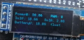
hi, i already found the problem resetting of arduino.. i just adjust the dead time of two pwm. now the problem is that the battery wont take much current and as can you see the link image is that the battery voltage goes up to 18v. i don't know if the battery is already broke. or may be other problems that i don't know yet. cant test for new battery since i don't have new battery for now.
You seem to have a 12-volt battery that reads 18 volts under load. That's odd.
Have you done a concurrent and independent test of the battery voltage, like with a real volt meter? Have you considered that the number being reported on the LCD is wrong?

 Facebook
 Google
 GitHub
 Linkedin