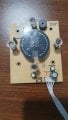
So voltage on these two pins is around 28.8, and it's kinda dancing like 28.7 to 28.8...
So far I replaced diodes, capacitors, the coil, those 2 transistors, that chip... the only thing I didn't replace is that dark green capacitor and that light green inductor, also those two beige resistors, but i checkted them and they are ok...
also I tried Control board on 9V battery ( connected on same pins as where i measured voltage) and it worked, but when i connect it to the board, it just repeatedly beeps... I also tried to connect only those two pins to the board, same issue...
What I see, it's that there is ma voltage for AMS1117 3.3V is 15V, but the pins output ~28V... so could that be the issue, but then, wouldn't AMS1117 just burn out, or break, and the board wouldn't continuesly beep?
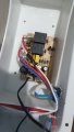
So I have Gorenje Panel heater "optiheat 2000 ewp" it have 2 boards, control board and power board, and it looks like something on power board went wrong.
This is the continuation of this thread here: Forum Thread
I have attached the photos of the board!
So far I replaced diodes, capacitors, the coil, those 2 transistors, that chip... the only thing I didn't replace is that dark green capacitor and that light green inductor, also those two beige resistors, but i checkted them and they are ok...
also I tried Control board on 9V battery ( connected on same pins as where i measured voltage) and it worked, but when i connect it to the board, it just repeatedly beeps... I also tried to connect only those two pins to the board, same issue...
What I see, it's that there is ma voltage for AMS1117 3.3V is 15V, but the pins output ~28V... so could that be the issue, but then, wouldn't AMS1117 just burn out, or break, and the board wouldn't continuesly beep?
What I see, it's that there is ma voltage for AMS1117 3.3V is 15V, but the pins output ~28V... so could that be the issue, but then, wouldn't AMS1117 just burn out, or break, and the board wouldn't continuesly beep?
The regulator could be outputting a low voltage - enough to beep but not enough to do anything useful... or a higher voltage, which means possibly the board is fried and all it can do is beep.
The regulator could be outputting a low voltage - enough to beep but not enough to do anything useful... or a higher voltage, which means possibly the board is fried and all it can do is beep.
Ouch, you're lucky the downstream MCU etc are still alive, but not for much longer I suspect, that'll be stressing them badly. Clearly the regulator is unhappy with that input voltage; it's in some strange world of its own. You need to check it with a 12v input from a wall-wart or LiPo battery pack that has sufficient current delivery capability, around 1A should do it, to see if it is actually working ok.
Ouch, you're lucky the downstream MCU etc are still alive, but not for much longer I suspect, that'll be stressing them badly. Clearly the regulator is unhappy with that input voltage; it's in some strange world of its own. You need to check it with a 12v input from a wall-wart or LiPo battery pack that has sufficient current delivery capability, around 1A should do it, to see if it is actually working ok.
Another thing, When i disconnect board, the volate is climbing to around 12-13 volts on pins 5-4, but when i connect the board its in milivolts... that is on 12V battery charger... So i don't know what is going on...
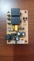
Soo, I measured in DC mode:
AG = 328V
BG = 328V
CG = jumping fast between 38V and 48V, like one second its 38V and another its 48, and it jumps like that...
G and pin next to C is 28V
Do you have an LCR meter to measure inductance? The only other reason for the output being wrong, assuming the chip isn't faulty, is a wrong inductor value - maybe it has an internal short.
 Facebook
 Google
 GitHub
 Linkedin