Anyone knows what this IC is?

Thread Starter

FlllP

Joined Jul 19, 2025
105
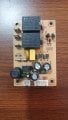
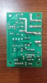
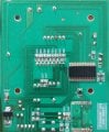
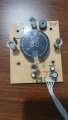
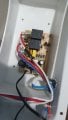
I have this IC on this board thats from panel heater that works with Tuya Smart... Tried searching online the marking, nothing came up... Heater is gorenje Optiheat 2000 ewp... and it stopped working. control panel is not turning on... So im trying to fix it... Thank you!20251030_190449.jpg
 

Attachments

Irving

Joined Jan 30, 2016
5,055
Check power supply first ( third photo). First of all, the yellow capacitor is suspicious
The one marked JURCC? Why, looks OK to me.

Clearly TS needs to check 12v rail is present at the relays and then trace through to the 5v regulator wherever that is - not obvious from those photos. A better pic of the relay/power board without the view being obscured by the mains wiring would help a lot.

@FlllP That chip on the main board is almost certainly a custom programmed MCU, so unlikely you'll find anything useful on it, but the fault is very unlikely to be anything to do with that, its going to be power supply related, so a little methodical measuring with a multimeter is the way to go with this - but we need much better/clearer photos, starting with that power board, both back and front please.
 

Thread Starter

FlllP

Joined Jul 19, 2025
105
The one marked JURCC? Why, looks OK to me.

Clearly TS needs to check 12v rail is present at the relays and then trace through to the 5v regulator wherever that is - not obvious from those photos. A better pic of the relay/power board without the view being obscured by the mains wiring would help a lot.

@FlllP That chip on the main board is almost certainly a custom programmed MCU, so unlikely you'll find anything useful on it, but the fault is very unlikely to be anything to do with that, its going to be power supply related, so a little methodical measuring with a multimeter is the way to go with this - but we need much better/clearer photos, starting with that power board, both back and front please.
I find around climbs from 12v to 20V and up... AMS1117 3.3 vas shorted and i replaced it, resistors and capacitors on control board seems fine... and 3v on the wifi board... here are the images of the power board
@Pyrex Yellow capacitor on board reads around 88nF and its JURCC X2-104K MPX/MKP, doesn't show continuity on it...

1761920286681.png
 

Attachments

panic mode

Joined Oct 10, 2011
4,918
the SOT89 part in lower left corner must be 3.3V regulator powering MCU and radio module. so "around 3V" is right.
capacitors are open circuit for DC so " JURCC X2-104K MPX/MKP, doesn't show continuity on it... " is fine.
MCU is nowhere to be found, one page suggested it is likely a 48MHz 8-bit MCU with 32k flash and 2k RAM.
 

Thread Starter

FlllP

Joined Jul 19, 2025
105
the SOT89 part in lower left corner must be 3.3V regulator powering MCU and radio module. so "around 3V" is right.
capacitors are open circuit for DC so " JURCC X2-104K MPX/MKP, doesn't show continuity on it... " is fine.
MCU is nowhere to be found, one page suggested it is likely a 48MHz 8-bit MCU with 32k flash and 2k RAM.
Yes, in the left corner its AMS1117 3.3V. not sure what voltage should be going into the MCU?
 

panic mode

Joined Oct 10, 2011
4,918
regardless if designing or troubleshooting, there is no way around datasheets.

and you need to measure at correct points:
1761925171142.png

output voltage need to match regulator, such as 3.3V in this case. so you need to measure that between GND and regulator output.

input voltage will be higher. you need to check the datasheet how much higher is ok.

according to datasheet, absolute maximum for that regulator is 15V before it is damaged.
1761925538076.png
 
Last edited:

panic mode

Joined Oct 10, 2011
4,918
in other words, if you are still getting 3.3V, you are lucky to have a specimen that survived higher input voltage (so far).
i would disconnect power to the regulator until cause of increased voltage is fund and corrected.
 

Thread Starter

FlllP

Joined Jul 19, 2025
105
regardless if designing or troubleshooting, there is no way around datasheets.

and you need to measure at correct points:
View attachment 358009

output voltage need to match regulator, such as 3.3V in this case. so you need to measure that between GND and regulator output.

input voltage will be higher. you need to check the datasheet how much higher is ok.

according to datasheet, absolute maximum for that regulator is 15V before it is damaged.
View attachment 358011
Between pins 1 and 2 is 0.3 mV and between pins 1 and 3 is 30-100mV... so Im not sure whats going on there...
 

Irving

Joined Jan 30, 2016
5,055
Hmmm, looks like that regulator is toast, which given its 15v max input isnt surprising.

As suspected the fault is in the little SMPS on the other board. It should be giving approx 12v not 22v. Be warned, there is 110 or 230v, depending on where you are, on that other board and no isolation. Fault finding could be harmful to your health.

Give me a few mins to work out where to go next...

But its likely the whole thing is toast.
 

Thread Starter

FlllP

Joined Jul 19, 2025
105
Hmmm, looks like that regulator is toast, which given its 15v max input isnt surprising.

As suspected the fault is in the little SMPS on the other board. It should be giving approx 12v not 22v. Be warned, there is 110 or 230v, depending on where you are, on that other board and no isolation. Fault finding could be harmful to your health.

Give me a few mins to work out where to go next...

But its likely the whole thing is toast.
I replaced AMS1117, but that didn't solved anything...
 

Thread Starter

FlllP

Joined Jul 19, 2025
105
Hmmm, looks like that regulator is toast, which given its 15v max input isnt surprising.

As suspected the fault is in the little SMPS on the other board. It should be giving approx 12v not 22v. Be warned, there is 110 or 230v, depending on where you are, on that other board and no isolation. Fault finding could be harmful to your health.

Give me a few mins to work out where to go next...

But its likely the whole thing is toast.
You mean the board with relays?
 

Irving

Joined Jan 30, 2016
5,055
yes. The 7-pin chip at the bottom is a little switched mode power controller, not sure which one yet. But there is upwards of 325v there before it becomes 12v...
 
Top