amplification -- newbie

Audioguru

Joined Dec 20, 2007
11,248
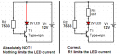
Your circuit has a saturated transistor which is a turned on switch. It is not a linear amplifier.

Look at the datasheet for the 2N2222 transistor or any other transistor.
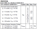
The hFE (beta) is spec'd when the transistor has plenty of collector to emitter voltage (10V) so it is NOT saturated.
The Collector to Emitter Saturation Voltage is spec'd as maximum when the base current is 1/10th the collector current (Hfe is not mentioned).

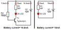
Your base resistor limits the base current to only 134th of the collector current so you are simply lucky that your transistor saturates better than most.

Some 2N2222 transistors saturate well in that circuit. Most will not because the 10k base resistor value is too high.
 

Attachments

Thread Starter

gerases

Joined Oct 29, 2012
186
I see. To summarize then:

So, when the resistance of the transistor is relative high (such that 10V is dropped around CE), there could be all these crazy gains (usually). Otherwise, when the transistor has almost no resistance (small voltage drop), the relationship of Ic to Ib is 10 to 1.

In switching applications it's the saturation that I should be shooting for and so I would divide the current of the load by 10, etc.

When doing amplification stuff, where input current should be proportionally "amplified", we use the Hfe values.

The fact that I received such an unusual result when the transistor was saturated is indeed a-typical.

I'm curious if I used the 10 to 1 approach in choosing the resistor, what would have happened. I need to check it out tonight. But theoretically it would be this:

Assuming I want 15mA in the LED:

Required Ib = 0.015 / 10
Required resistor: (12 - 0.7) / Required Ib = 7533 Ohms [ I know, I know it's not standard :) ]
Ib current = .907 / 7533 = 0.12 mA

Which is still below the maximum base current (200mA according to my datasheet)

Is that correct? I'm dying to try it tonight.

The interesting thing is I was crazy enough to measure the current directly between the emitter and the LED. It read 76mA and the LED survived too.

PS.: also interesting is that when picking the base resistor you assume that the Collector-Emitter is not passing anything through. So, a significant voltage drop will occur on the base resistor, but once the current is flowing between C and E, the picture is different in that the resistor will have a minimum V drop (I guess the less, the more saturated the transistor is).

Let me know if I'm still off in my understanding.
 

Audioguru

Joined Dec 20, 2007
11,248
So, when the resistance of the transistor is relative high (such that 10V is dropped around CE), there could be all these crazy gains (usually). Otherwise, when the transistor has almost no resistance (small voltage drop), the relationship of Ic to Ib is 10 to 1.
No.
Some transistors saturate well with a small base current as you had. But if you want EVERY transistor to saturate well then calculate the base resistor so that the base current is 1/10th the collector current.

In switching applications it's the saturation that I should be shooting for and so I would divide the current of the load by 10, etc.
Yes.

When doing amplification stuff, where input current should be proportionally "amplified", we use the Hfe values.
Yes, but hFE is different for each transistor so negative feedback is used to reduce the difference.

The fact that I received such an unusual result when the transistor was saturated is indeed a-typical.
Yes it was very unusual.

Assuming I want 15mA in the LED:

Required Ib = 0.015 / 10
Required resistor: (12 - 0.7) / Required Ib = 7533 Ohms [ I know, I know it's not standard :) ]
Ib current = .907 / 7533 = 0.12 mA
No.
The emitter is supposed to be connected to 0V, not to an LED and resistor.
Then the base voltage is only 0.7V. The base resistor has 12V - 0.7V= 11.3V across it and its value is 11.3V/1.5mA= 7533 ohms.

The interesting thing is I was crazy enough to measure the current directly between the emitter and the LED. It read 76mA and the LED survived too.
The poor LED was overloaded and it will never be like a new one. You forgot to connect a current-limiting resistor in series with the LED.

You cannot rely on the transistor to majically limit the current because each transistor is different and temperature change also affects how much it turns on.

Also interesting is that when picking the base resistor you assume that the Collector-Emitter is not passing anything through. So, a significant voltage drop will occur on the base resistor, but once the current is flowing between C and E, the picture is different in that the resistor will have a minimum V drop (I guess the less, the more saturated the transistor is).
Only with your weird circuit that used the transistor as an emitter-follower, not as a switch. A switch has the LED and its current-limiting resistor connected to the collector, not to the emitter. The emitter is connected to 0V. See my attachment:
 

Attachments

Thread Starter

gerases

Joined Oct 29, 2012
186
Thanks, AG and Weyne for putting up with my questions.

Only with your weird circuit that used the transistor as an emitter-follower, not as a switch.
Please note that the circuit is not mine. I'm following a book -- it's my second week in electronics, period. Before that, last time I did anything with electronics was in high school at physics lessons -- and it was more than 20 years ago.

Unfortunately, the book leaves out too much unsaid assuming, probably, that the student will just be content with general ideas at this point. I however want to know everything. Luckily, you guys have been more than generous with your time. Can't thank you enough.

The poor LED was overloaded and it will never be like a new one. You forgot to connect a current-limiting resistor in series with the LED.
No, I didn't forget to put a resistor there. I was experimenting and I was ready for the LED to blow out, but it didn't. Still hasn't. RadioShack must put some magic in their parts -- crazy low saturation transistors, LEDs that will take 76mA without any visible aftermath.

Only with your weird circuit that used the transistor as an emitter-follower, not as a switch. A switch has the LED and its current-limiting resistor connected to the collector, not to the emitter.
See, that's what I'm saying to myself as well, why did the author put together such a full of underwater stones circuit? Don't get it.

But I'll be damned, I rewired the circuit the way you suggested connecting the load (LED + R1 + R3) to the collector and grounding the emitter. Now all the voltage drops is what I expected originally from the emitter-follower arrangement (not knowing of the emitter-follower caveat). This new version drops 12V to 0 twice: once between R2 and the base and one more time between the collector and emitter. They are really two different circuits now! Does it mean that if I used a 12V battery (instead of an AC supply), it would drain faster because essentially two different loads would be connected to it?

The emitter is connected to 0V. See my attachment:
Looks great and thank you. I didn't understand though, why you included the one on the left? Because of my experiment with the LED?
 

Thread Starter

gerases

Joined Oct 29, 2012
186
Got another related question. Please take a look at this schematic ignoring the circuit at the top (with an LED).

http://examples.oreilly.com/9780596153755-files/mkel_02/mkel_02_108.pdf

The bottom circuit contains a PUT based oscillator the output of which is amplified by a transistor. As you can see there's a 1K resistor connecting the oscillator and the transistor. First I measured the current in the oscillator, which came to be 0.01mA. Then I measured the current in the transistor circuit, which read 1.45mA, which is a 145 current increase. So, I decided to experiment a little further by reducing the 1K resistor to a 10 Ohm resistor. I know, I know -- dangerous, but I'm playing around at this point.

To my surprise the current fell to 0.75mA. Removing the resistor completely had the same effect -- 0.76mA. I thought by reducing the resistance on the base, there will be more current there, and hence more amplification. Especially since the transistor is capable of more than 145.

My question is: why did the current fall?

Also interesting is that the B-E junction of the transistor read 0.435V in all cases. I thought that the transistor will only open at 0.6 and more. Or is that for saturation only?

Actually it's interesting how it got to be 0.435V there because my below-amateur thinking tells that the output of the oscillator should produce at least 2V, which should be enough for the base of the resistor to be at 0.6V.
 

Audioguru

Joined Dec 20, 2007
11,248
The maximum allowed current in the PUT is only 150mA so reducing its series output resistor is overloading it and is overloading the base of the transistor. DONT DOO DAT!

You CANNOT measure very short duration voltage or current pulses with a multimeter. It measures slowly so it shows the AVERAGE voltage or current which are zero for most of the time. The peak voltage and current are much higher.
Reducing the important series output resistor allows the timing capacitor in the PUT oscillator to discharge a little faster. Therefore the average voltage and current are less.
 
Last edited:

Thread Starter

gerases

Joined Oct 29, 2012
186
Cool, thanks for the explanation of what's going on.

Speaking of PUTs, how are the programming resistors selected? I noticed that it's the 27K that actually sets the threshold, but let's say I wanted the threshold to be 2V, how would I go about it mathematically? I can't find this info anywhere.

PS: it (the threshold) seems to be calculated as Vsupply * R2 / (R1 + R2)
PSS: http://examples.oreilly.com/9780596153755-files/mkel_02/mkel_02_103.pdf

Why isn't there a current limiting resistor with the LED in this simple circuit? After the LED opens with each pulse, its resistance is almost zero, right? So, wouldn't it overload the PUT and LED for that matter?
 
Last edited:

Audioguru

Joined Dec 20, 2007
11,248
Speaking of PUTs, how are the programming resistors selected? I noticed that it's the 27K that actually sets the threshold, but let's say I wanted the threshold to be 2V, how would I go about it mathematically? I can't find this info anywhere.
TWO resistors set the reference voltage as a voltage divider. The 27k resistor has a 15k resistor in series. Their total resistance is 42k so if you want a reference of 2.0V then simply use Ohm's Law to calculate it.
The current in the 27k resistor is 2V/27k= 74uA. The voltage across the 15k resistor is 15k x 74uA= 1.11V. Then the power supply voltage is 2.0V + 1.11V + a diode voltage drop (0.65V)= 3.76V.
 

Thread Starter

gerases

Joined Oct 29, 2012
186
TWO resistors set the reference voltage as a voltage divider. The 27k resistor has a 15k resistor in series. Their total resistance is 42k so if you want a reference of 2.0V then simply use Ohm's Law to calculate it.
The current in the 27k resistor is 2V/27k= 74uA. The voltage across the 15k resistor is 15k x 74uA= 1.11V. Then the power supply voltage is 2.0V + 1.11V + a diode voltage drop (0.65V)= 3.76V.
Are you calculating the power supply voltage required? I was more interested in:

If we have a 6V supply and a needed reference voltage of 2V, how do we calculate the values of the resistors?

It seems that the first resistor should be taken as an arbitrary value of say 15K and to get the second the following equation should be solved for R2:

(R2 / (15,000 + R2)) * 6 = 2
Bla, bla, bla: R2 = 7500

How crazy is my solution?
 
Top