amplification -- newbie

Thread Starter

gerases

Joined Oct 29, 2012
186
Got a very simple question. I'm going through an Electronics book (Make Electronics).

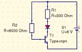
The project I'm on is an PUT driven oscillator and the first version of it is here:

http://examples.oreilly.com/9780596153755-files/mkel_02/mkel_02_108.pdf

The drawing actually has two circuits on it. Ignore the top one (with a 2.2 microfarad capacitor) and please look at at the second one (the one with a 0.0047 capacitor).

As you can see the output of the PUT is fed through a 1K resistor into the base of a transistor (2222N I think). This I do get because the output from the PUT will be relatively low and the transistor will "amplify" that signal.

If however you look at this version of the schematic:

http://examples.oreilly.com/9780596153755-files/mkel_02/mkel_02_114.pdf

You will see that the output of the first transistor is fed into the base of another transistor to "amplify" the signal further.

What I don't get is: why not just manage with one transistor because there's only one power supply and the maximum current we will get will be 6V divided by the resistance. Why add another transistor and not just lessen the resistance of the output of PUT?

I.e., couldn't I just replace the 1K resistor on the output of the PUT with a 100 Oms resistor?

Why have 2 or 3 or 5 stages of amplification at all - especially if the max we can get is 6V or whatever the power supply can provide?

I'm a total newbie. So bear with me.
 

wayneh

Joined Sep 9, 2010
18,104
It's about current. A rule of thumb is that a transistor can control about 10X more current than is fed its base. Or, the base current will be about 10% of the collector-emitter current. If you need a "large" output current from a "small" input, you need more than one level of amplification.
 

Thread Starter

gerases

Joined Oct 29, 2012
186
I see! So, at each stage we can put more into that transistor's base and the current is always in relation to the base voltage. Sweet. Thanks a bunch!!!

The only question I have now is how the heck to calculate the needed resistors. . Let's say I have a 6V power supply, a transistor, and an LED. What would be the required resistor on the base to keep the LED half way bright?

But even without answering this question, I'm a happy camper :)

Thanks!!!
 

wayneh

Joined Sep 9, 2010
18,104
Well first, you want a current-limiting resistor in series with the LED. When the transistor is fully "on", it will have some resistance but might as well be a short. That would put 6V across the LED and toast it. A 270Ω or 330Ω resistor would be fine. Even 100Ω may be fine, but lower ohms equals higher current equals riskier (for your LED) without testing.

If you suppose "half bright" is 10mA, then in theory you need about 1mA on the base of the transistor to be sure it will allow that 10mA to flow. So you need to drop 6V across a resistor at 1mA. (You can assume the base is effectively grounded for this.) V = IR 6 = 0.001R R=6000Ω.
 

Thread Starter

gerases

Joined Oct 29, 2012
186
Well first, you want a current-limiting resistor in series with the LED. When the transistor is fully "on", it will have some resistance but might as well be a short. That would put 6V across the LED and toast it. A 270Ω or 330Ω resistor would be fine. Even 100Ω may be fine, but lower ohms equals higher current equals riskier (for your LED) without testing.

If you suppose "half bright" is 10mA, then in theory you need about 1mA on the base of the transistor to be sure it will allow that 10mA to flow. So you need to drop 6V across a resistor at 1mA. (You can assume the base is effectively grounded for this.) V = IR 6 = 0.001R R=6000Ω.
But what are these numbers about transistors I see 1:240, etc? For example, in the book I'm using the author says just that: the 2N4401 transistor is 1 to 240 amplification. Or is that something else?

I understand about the resistor on the LED well enough, but theoretically by assuming (limiting) the current through the LED to a low value and by dividing that value by 10 one could arrive at a correspondingly large resistor (using the calculation technique you've demonstrated), which would make the Emitter-Collector current acceptable, right? I know it's good practice to put a resistor there, but still?

Also, if we do put a resistor on the LED, does that resistor influence the calculation of the base resistor somehow?

Finally, and I apologize for all the questions, where in the datasheet on an LED should I look for the optimal current through it? Like in this case you assumed 10mA would be OK.
 

Adjuster

Joined Dec 26, 2010
2,148
High gain values are normally quoted for transistors when used in their active amplifying or linear mode. The rule - of - thumb 10 times is used for hard switching when a transistor is required to be fully switched on. More rarely a rather higher value typically up to 20 or so may be possible, particularly if sanctioned by manufacturers data.
 

wayneh

Joined Sep 9, 2010
18,104
But what are these numbers about transistors I see 1:240, etc? For example, in the book I'm using the author says just that: the 2N4401 transistor is 1 to 240 amplification. Or is that something else?
It could be voltage gain instead of current gain. But anyway as noted current gain can be much greater than 10, but will be closer to 10 when the transistor is being saturated to act as an on/off switch. If you use a large base resistor and don't turn the transistor full on, the current gain will be larger.

I know it's good practice to put a resistor there, but still?
Still what? I don't get the question. The resistor to limit LED and C-E current is critical unless there is another feedback to keep that current from running away.

Also, if we do put a resistor on the LED, does that resistor influence the calculation of the base resistor somehow?
Only in the sense that it caps the C-E current, and therefore the max base current needed to achieve that.

Finally, and I apologize for all the questions, where in the datasheet on an LED should I look for the optimal current through it? Like in this case you assumed 10mA would be OK.
A datasheet should list the absolute maximum continuous current. For a common LED, this may be listed as 25-30mA. Folks usually aim to run these at no more than 20mA, so that they last longer. (And a general safety factor of never running any component too close to its spec, since many specs are, shall we say, "generous".)
 

Adjuster

Joined Dec 26, 2010
2,148
Many typical LEDs, (not super - small or high power) would have maximum continuous currents at normal working temperatures around 20mA, maybe up to 30mA, so 10mA should be a pretty good guess for running very conservatively, really about half - power. Manufacturers normally give at least the maximum current though, it should be given fairly explicitly.
 
Last edited:

Thread Starter

gerases

Joined Oct 29, 2012
186
It could be voltage gain instead of current gain.
You are probably right.

Still what? I don't get the question. The resistor to limit LED and C-E current is critical unless there is another feedback to keep that current from running away.
Yes, I get it. Forget that part of my question. I overheated yesterday :)

But I do have another question about the values of the resistors. Please take a look at this schematic:

https://docs.google.com/open?id=0B8FF7jZJwuoUQ3JjQ2JibWxrTTA

These is the scenario we've been talking about -- sorry if I connected smth wrong.

OK, so when the transistor is on, we can ignore it in the calculation of the total resistance of the circuit. So we're left with two resistors connected in parallel (?) and so the total current in the circuit will be:

6 / (300 * 6000 / 300 + 6000) = 21 mA

Thus wouldn't it be correct to put a 670Ω resistor instead of the 300?

6 / (670 * 6000 / 670 + 6000) = 9.95 mA?

Just thinking aloud. And I'm probably wrong :)

Thoughts?
 

Audioguru

Joined Dec 20, 2007
11,248
Please take a look at this schematic:
It is a horrible schematic with a few parts upside down. I fixed it.

OK, so when the transistor is on, we can ignore it in the calculation of the total resistance of the circuit. So we're left with two resistors connected in parallel (?)
Nothing is in parallel. Your calculations do not make sense.
When the transistor is turned on then its collector to emitter has a very low resistance with a very low voltage drop. The red LED is about 2V so the 300 ohm resistor limits the LED current to (6V - 4V)/300= 6.7mA.

The base-emitter voltage is about 0.7V so the base resistor provides a base current of (6V - 0.7V)/6k= 0.88mA which is plenty to saturate the transistor.
6k is not a standard value. A normal 6.8k resistor should be used.
 

Attachments

Thread Starter

gerases

Joined Oct 29, 2012
186
Got it. Despite the boorish way of delivering the explanation, I nevertheless found it (the explanation) extremely valuable.

One thing though: why the 6000 resistor is not taken into account for determining the total resistance of the circuit but is only factored in for dropping the voltage on the base? I kinda get it but kinda don't.
 

wayneh

Joined Sep 9, 2010
18,104
Your calculations were sort of correct but, as AG noted, did not account for the voltage drops across the LED or the base-emitter. The latter error is small but the former is big.
 

Thread Starter

gerases

Joined Oct 29, 2012
186
Your calculations were sort of correct but, as AG noted, did not account for the voltage drops across the LED or the base-emitter. The latter error is small but the former is big.
I agree. Now, AG says that 0.88 mA is plenty to saturate a transistor. Is that a datasheet value?
 

Audioguru

Joined Dec 20, 2007
11,248
Now, AG says that 0.88 mA is plenty to saturate a transistor. Is that a datasheet value?
The datasheet value for the base current of most saturated (turned on hard) transistors is 1/10th the collector current.
The collector current is 6.7mA so the base current should be 0.67mA (or a little more).
 

Thread Starter

gerases

Joined Oct 29, 2012
186
I did a test at home for this schematic from the book:

http://examples.oreilly.com/9780596153755-files/mkel_02/mkel_02_086.pdf

And I was very surprised at the results. The schematic is based on the 2N2222 transistor. First of all, the Hfe of this transistor is from 100 to 240. I was expecting 10 or so. That's the first surprise. The other is the voltage drop between the R2 and the base.

First the numbers for the components:

R1: 121 Ohm
R2: 10K
R3: 691 Ohm
Power supply: 12V DC

The voltage drop on R2 when the LED is on full blast is 0.9V

The other voltage drops are a little more understandable:

R1: 1.475V
R3: 8.41V
LED: 2
Base-Emitter: 0.683

I also measured the current:

Ibase = 0.09mA
Icollector = 12.60mA

So, how is the drop on R2 is explained (I expected it to be much higher)?

What about the 140, 240 current gains versus the 10-times gains we discussed yesterday?
 

wayneh

Joined Sep 9, 2010
18,104
That's called an emitter follower arrangement, because the emitter is not tied to ground but will instead float up and down depending on the current across R3 and the load. Notice how the base-emitter voltage stays a predictable 0.7V.

From your measurements, the emitter was at 2+8.41 = 10.41V. Adding the 1.475 for R1 gives 11.885, leaving only about 0.1V across Q1 if the supply was truly 12.00V. Q1 was indeed full on, or nearly so.

You're correct that you had just under 0.1mA base current and a current gain of 140.

If that surprises you, then you have misunderstood us. The rule-of-thumb is sort of the worst case minimum you use in a design to ensure that the transistor turns fully on when you require that to happen, perhaps when the transistor is conducting near its maximum safe current level. It doesn't mean the current gain will always be merely 10. If you designed for a base current of 1% of the C-E current, your circuit may not always work and may be "pinched" by the base current bottleneck. Using 10% ensures plenty of current without much risk of burning out the base circuit.
 

Audioguru

Joined Dec 20, 2007
11,248
Where did you find the weird resistor values?
Oh, maybe you used a 120 ohms resistor for R1 that measured 121 ohms?
Then you used a 680 ohms resistor for R3 that measured 691 ohms?

The emitter of the transistor is at +10.41V and the base is 0.683V higher so the base is +11.093V. Then R2 has only 0.907V across it. The base current is 0.907V/10k= 90.7uA.
The collector current is 12.19mA.

You are lucky that your transistor saturates with a base current that is very small. Since every transistor is different then the weakest (but passing one) needs a base current that is much higher for it to saturate.
 

Thread Starter

gerases

Joined Oct 29, 2012
186
Where did you find the weird resistor values?
Well, I'll be honest, that's how I decoded the values by the colors. But the problem is I have a problem with seeing colors sometimes and two, I don't know the standard values, all kinds of numbers look OK to me. I rely on the meter to see if I'm within range of my decoding. Maybe you could tell me which are standard values or what the principle is?

The emitter of the transistor is at +10.41V and the base is 0.683V higher so the base is +11.093V. Then R2 has only 0.907V across it. The base current is 0.907V/10k= 90.7uA. The collector current is 12.19mA.
I understand your logic. I almost have it. It's counter intuitive for me that such a large resistor (R2) has the least voltage drop, I don't know why.

But most importantly, this kind of screws up my understanding of how to pick a resistor for the base especially since the amplification depends on the load on the emitter. Before, you guys said that I just take my required current in the load, divide by 10, then do this: Vs - 0.7 / R = Ib (i.e., Ic / 10). But looking at the datasheet for this transistor, it doesn't have a 1-value amplification. It's a range from 100 to 300.

So, in the case of this circuit and this transistor, how would you arrive at the 10K resistor?

I'm a newb, what can you do :)
 
Top