Does the LED light at all when the receiver is not locked?
[/QUOTE]
LOCK is signal lock.
Pin 16 is for signal
When I connect dish coax to stb, fd650 ic outputs 0.3-1.2v on pin 16. This is the signal led. The led does not flicker. It lights at medium intensity and constant.
So, the idea here is that the output of pin 16 might be floating when it is not pulled high, so a pulldown might fix it. That's why I was asking if the LED glows, even very faintly, when not it is not being actively lit. without the opto in place, do you see any light from the LED (in say, a darkened room)?
Well, I just don't seem to be able to get a complete picture of your problem. It isn't coming together for me. I do hope you figure it out. The one, probably useless thing, I would try is to put the opto in parallel with the existing LED, not series.
In any case, if I see anything that gives me more of a clue, I will chime in. Good luck!
Examining that schematic of the LED portion, it looks to me like the display is scanned. That is why the driver has both digit enable and segment drive outputs. see the FD6505 datasheet GIF posted a while back. So the LED id actually only driven for a very short time, while it is enabled every scan. That is a nice trick to save processor I/O lines. So the work around that is to replace the green LED, "D2" with the LED in the opto isolator, so that the isolation can stay isolated. THEN the output transistor in the opto can drive another IC one-shot with a longer time so that when the LED drive is on the OS output will be constant. AND that same one-shot can enable the sounder (buzzer).
Either a 555 or a CD4098, I think, multivibrator, can serve to stretch the pulses into a constant "ON" signal . You might even be able to do it with just a transistor and a capacitor.
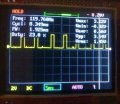
The scope trace in the previous comment verifies what I said!! The output is scanned. And scanned displays can be a serious challenge to work with, and they often generate hard to tack down electrical noise in the system.
Here is a description of the circuit, I still don;t have graphics capabilities.
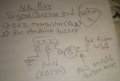
From the opto-isolator NPN output transistor: The collector would tie to the +5 volt supply, and the emitter will connect to a resistor (4r7K ohms) to the 5 volt common. This emitter point will also connect to the base of an NPN transistor 2N3904) and a fairly high value capacitor, (47Mfd), with the cap negative to common. There may need to be another resistor in series with that base connection, not sure. The emitter of that 2N3904 will connect to common thru a 100 ohm resistor. From the collector of the 2N3904 will be the negative terminal of that electronic sounder device. The positive terminal of the sounder device will connect to the +5 volt source., if it is a 5 volt sounder, otherwise + 12, if it is a 12 volt unit. The LED, with a 270 ohm series resistor, will also connect between the collector and the +5 source.
The operation will be that when the signal that would light D2 is sent, the opto will switch on briefly and charge the capacitor so that a positive base voltage will turn on the 2N3904. The transistor will the conduct and drive the sounder and the LED.
When that signal is not present the 4.7K ohm resistor will discharge the 47Mfd capacitor and the 2N3904 will be biased off, stopping the sound
It may be prudent to review and reattempt the suggestions given by the users here. Are you sure you wired everything as directed? Are you sure you have correctly identified the parts involved and have found their datasheets/schematic to be accurate to your device? You mentioned that your driver is "slightly different" than what you presented. The error may be in your analytical approach. The users here are intelligent folk, you could also scrap everything and start over with fresh eyes.
I removed the led and soldered the buzzer in its place. The sound was low but it made the same sound. I can't fully explain it but it sounds like the led is being switched on and off rapidly. It sounds like it is cycling. So maybe thats why the buzzer makes that TRRRR sound which could be cycling/startup.
Cheap multimeter showed a fluctuating voltage so I added a electrolytic capacitor but this time the buzzer made no noise.
I tried using NPN as a switch and the result is the exact same.
If the issue is seeing the LED in daylight, have you considered a non invasive technique to make the distinction between on and off more prominent? Perhaps a colour filter or paper towel tube wrapped in black tape, a sort of viewing scope? I can understand why a buzzer would be ideal but it's possible the designer intended the LED to operate in a specific way. Another thing to consider is the information you have available may not reflect the internal components. One user made a post recently where the replacement component did not match the description on the face plate. As you can imagine this makes things potentially doomed to fail in the absence of extreme vigilance.
I removed the led and soldered the buzzer in its place. The sound was low but it made the same sound. I can't fully explain it but it sounds like the led is being switched on and off rapidly. It sounds like it is cycling. So maybe thats why the buzzer makes that TRRRR sound which could be cycling/startup.
Cheap multimeter showed a fluctuating voltage so I added a electrolytic capacitor but this time the buzzer made no noise.
I tried using NPN as a switch and the result is the exact same.
The reason that it sounds like it is being switched on and off rapidly is exactly what is happening. The display driver enables each character one at a time and the same set of drivers delivers the segment drive for that character. GO BACK and look at the outputs for that device! There are both digit enabler and segment drive. Then look up multiplexed displays or scanned displays. That same output is also driving other things during the other time slots. Read the device description and application information to understand what that FD650 is doing.
So if the buzzer buzzes at the frequency you witnessed, what's wrong with that as the indicator? I thought the goal was to replace light with sound.. maybe I'm missing something..? I'm referencing your results from post #20.
I took out the stb out yesterday and started tinkering with it again. This time took out my breadboard also. I placed the optocuplar pin1/2 across the led diode of the stb. Added a 5v supply. Placed the active buzzer on the photoconductive side. Same 120hz noise.
I thought, let's add a filter cap across the buzzer and baam!! it worked. 2200uf at first which left a buzzer delay. Then got down to a tiny 22uf.
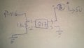
Here is a photo of the buzzer diagram usually implemented in sat finders. The same 16pin fd650 led driver is used which drives the buzzer/beeper.
Only difference is that the sat finder makes a beeping sound(25% duty cycle 2.1vpp) instead of a continuous beep. This beep sound changes to a continuous beep(50% duty cycle 2.1vpp) once it locks onto the Satellite.
I suspect it is a PWM signal driving the buzzer through a MOSFET.
 Facebook
 Google
 GitHub
 Linkedin
 80.8 KB Views: 5