 Facebook
 Google
 GitHub
 Linkedin
Hello,
This is a schematic that I have been irritating another forum way too much about. I want to spare the sanity of the people over there and ask this one single question here. No PCB routed yet - just working on schematic.
Project background: I am creating a simple timer. I will be using this timer daily, but I will be the only one using it. Hence, it is a hobbyist project. Circuit needs to be reliable enough for daily use but doesn't have to go overkill.
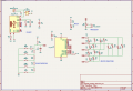
What I am asking about: I am basically changing the schematic below:

to include a USB-C power input. USB-C will be used for power only - no data.
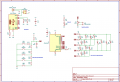
Here is what I have come up with for adding USB-C:

NOTE 1: I know that this schematic is very bad if I were to connect both J1 and J2 to power at the same time. However - J1 is only intended as I backup if I (as a beginner) f*** up the USB-C part of the circuit. I guarantee that these two will NEVER be connected to power at the same time.
NOTE 2: Just as a disclaimer, I have changed some resistors on BTN_INPUT_MULTIPLEXING between the first and second image. R12 is wrongly placed in the first image (marked Rev 0.2). I also changed the labels of the resistors on that part of the circuit. But that shouldn't matter for the USB-C part")
My questions:
- Have I gotten the USB-C circuit correct? Of course in general. But particularly, I am concerned about:
- Will PWR_SWITCH work with USB-C? I see no reason why it shouldn't, but I have never worked with USB-C before so I wanted to be sure.
- After some advice from people online (but without accounting for USB-C) I added a 4.7uF decoupling cap intended to be close to the power input. You can see it as C3 on the board. Does adding USB-C change anything regarding this? I.e. should I reconsider or change my caps. I know the spec allows for caps (up to a certain value, which I am not exceeding).
- Now that freakin shield connection. Am I safe with what I am doing right now? As I said there is no data transfer, USB is only used for power. There are a million different suggestions for how to wire it online. Spec says it should be connected to GND. Some recommends a cap and resistor in parallel - I would imagine it is a bit overkill for a hobbyist project. This hobbyist-geared tutorial: https://dubiouscreations.com/2021/04/06/designing-with-usb-c-lessons-learned/ does not even use a resistor (just connecting it to GND directly). The 1M resistor idea is from this tutorial: https://www.pcbway.com/blog/PCB_Design_Tutorial/How_to_add_USB_C_to_your_projects.html.
This is a schematic that I have been irritating another forum way too much about. I want to spare the sanity of the people over there and ask this one single question here. No PCB routed yet - just working on schematic.
Project background: I am creating a simple timer. I will be using this timer daily, but I will be the only one using it. Hence, it is a hobbyist project. Circuit needs to be reliable enough for daily use but doesn't have to go overkill.
What I am asking about: I am basically changing the schematic below:
to include a USB-C power input. USB-C will be used for power only - no data.
Here is what I have come up with for adding USB-C:
NOTE 1: I know that this schematic is very bad if I were to connect both J1 and J2 to power at the same time. However - J1 is only intended as I backup if I (as a beginner) f*** up the USB-C part of the circuit. I guarantee that these two will NEVER be connected to power at the same time.
NOTE 2: Just as a disclaimer, I have changed some resistors on BTN_INPUT_MULTIPLEXING between the first and second image. R12 is wrongly placed in the first image (marked Rev 0.2). I also changed the labels of the resistors on that part of the circuit. But that shouldn't matter for the USB-C part
My questions:
- Have I gotten the USB-C circuit correct? Of course in general. But particularly, I am concerned about:
- Will PWR_SWITCH work with USB-C? I see no reason why it shouldn't, but I have never worked with USB-C before so I wanted to be sure.
- After some advice from people online (but without accounting for USB-C) I added a 4.7uF decoupling cap intended to be close to the power input. You can see it as C3 on the board. Does adding USB-C change anything regarding this? I.e. should I reconsider or change my caps. I know the spec allows for caps (up to a certain value, which I am not exceeding).
- Now that freakin shield connection. Am I safe with what I am doing right now? As I said there is no data transfer, USB is only used for power. There are a million different suggestions for how to wire it online. Spec says it should be connected to GND. Some recommends a cap and resistor in parallel - I would imagine it is a bit overkill for a hobbyist project. This hobbyist-geared tutorial: https://dubiouscreations.com/2021/04/06/designing-with-usb-c-lessons-learned/ does not even use a resistor (just connecting it to GND directly). The 1M resistor idea is from this tutorial: https://www.pcbway.com/blog/PCB_Design_Tutorial/How_to_add_USB_C_to_your_projects.html.
Attachments
-
 40.4 KB Views: 7
 -
 112.2 KB Views: 7


