I use a open source dvb-s2 set top box. I input the specific transponder freq(from lyngsat) of the particular satellite. I use an app(satellite pointer) which uses my location and launches the camera app and it overlays satellite constellations(geostrategic orbit) over it. I point it at the sky and get an estimate of where I need to point my dish. I already input the transponder freq in the set top box and launch the signal screen. I start rotating half inch and scan vertically. Nothing. Rotate another half inch and can up to down again. It takes about 15min
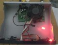
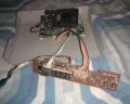
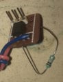
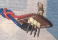
On the front panel, there is a driver chip(fd650) which is being controlled by the main board(gx6605s) using two data lines(clock and data). The led is connected to pin16 of fd650. Cathode goes straight to ground on my board.
Attached a rough schematic of fd650 I found on net. Mine is slightly different.
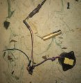
Buzzer is a self driving piezo speaker which works on 5vdc
Did you try connecting that buzzer directly across the LED? If that does not work, then try it with one side of the LED disconnected.
AND have you verified that the negative lead of the LED goes directly to the receiver power common? Sometimes the resistor would be in the LED negative lead, it makes no difference which lead has the resistor.
But now looking at the circuit I see that it is a scanned display. That optoisolator will not help much, nor at all with the connection scheme shown.
I am having some trouble being certain that I understand your descriptions of the problem and the steps you are taking to solve it. Could you draw a schematic of the relevant parts? It can be hand drawn, I just don't know if I am understanding what you are describing.
Did you try connecting that buzzer directly across the LED? If that does not work, then try it with one side of the LED disconnected.
AND have you verified that the negative lead of the LED goes directly to the receiver power common? Sometimes the resistor would be in the LED negative lead, it makes no difference which lead has the resistor.
IF the green LED is the one marked as D2 in the circuit in post #31 then the problem is obvious, which is that it is a scanned display and the buzz is the scanning frequency. Is the meter an actual analog meter or is it on the LCD screen? Since we now know that the LED is part of a scanned display it is not likely that watching the LED with the circuit shown will be useful.
At this point some other means to monitor the signal strength is required.
Do you have a schematic of the receiver circuit? or even a block diagram??
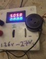
The front panel display is a 4 digit seven segment display.
My stb didn't have a signal led. But I studied another stb which had the same main board but different front panel. That stb had a signal led. I traced the lines and figured out that pin16 of fd650 was outputting to the signal led. So I added the led to my box.
 Facebook
 Google
 GitHub
 Linkedin