 Facebook
 Google
 GitHub
 Linkedin
I've been working on this for the past few hours and I'm at my wits end.
Basically, I'm trying to amplify an input voltage with a 100-ish gain using an AD8226 on a breadboard. I'm using a +/- 5V supply to power and op amp and using a 10 mV test for the input. I'm also using an oscilloscope to measure the output voltage, but the output reading is nowhere close to what I should be getting.
For example, a 10 mV input generates a 1.280 V reading, but a 20 mV input generates a 1.680 V outcome, and a 30 mV input generates a 1.760 V output and so on.
I've tried different AD8226 chips and I've been getting the same result. I'm thinking maybe my circuitry is wrong, but I haven't been able to find out what's wrong with it.
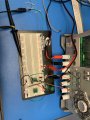
Any help would be greatly appreciated, this has been a gigantic pain. Here's a pic.
Red = S+
Black = S-
Green = ground
Light orange = Vin+
Dark orange = Vin-
Basically, I'm trying to amplify an input voltage with a 100-ish gain using an AD8226 on a breadboard. I'm using a +/- 5V supply to power and op amp and using a 10 mV test for the input. I'm also using an oscilloscope to measure the output voltage, but the output reading is nowhere close to what I should be getting.
For example, a 10 mV input generates a 1.280 V reading, but a 20 mV input generates a 1.680 V outcome, and a 30 mV input generates a 1.760 V output and so on.
I've tried different AD8226 chips and I've been getting the same result. I'm thinking maybe my circuitry is wrong, but I haven't been able to find out what's wrong with it.
Any help would be greatly appreciated, this has been a gigantic pain. Here's a pic.
Red = S+
Black = S-
Green = ground
Light orange = Vin+
Dark orange = Vin-
Attachments
-
 1.9 MB Views: 12
 -
1.5 MB Views: 10


