Active Butterworth Bandpass Filter unexpected peak

Thread Starter

xenon_eleven

Joined Jan 3, 2021
3
I am currently trying to design a bandpass filter in a simulator for a university assignment to the following criteria:
  • Frequencies below 1KHz and above 250KHz should be attenuated.
  • Note that you will need to calculate the cut off frequencies given the pass band (1KHz to 250KHz) should not be attenuated.
  • This filter should have roll off of -40dB per decade.
  • The filter also needs to have a variable gain for the pass-band, of between 0dB and 10 dB.
  • All capacitor and resistor values must be from the E12 E series.
  • Expected amplitude of the input voltage is up to 1 volt peak to peak, (you will need positive and negative supply; assume +9, –9 volts and ground are available, and can be connected to your circuit using an appropriate adaptor of your choosing.

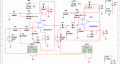
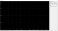
I have come up with the design seen in the attached image but I am getting an unexpected peak outside of my pass band (See Bode plots). I don't understand why this is happening or how to combat it. It seems linked to the amplification on the low pass filter as the peak gets much bigger when i use the variable resistor to increase the gain to 10dB compared to 0dB.

I have an idea it may have something to do with the op amp i am using. I'm not sure how to select an op amp that will still be effective for the requirements I have but not have this problem. Which parts of the op amp spec should i be looking at?

Whilst i am asking for help I also haven't been able to do the maths for calculating the cut off frequencies for no attenuation in the pass band, i have just used 1KHz and 250KHz as my cut off frequencies. Is it possible to explain the maths to work out the cut off frequencies so i can do that?

If anyone takes the time to read thank you!
 

Attachments

Papabravo

Joined Feb 24, 2006
21,225
The properties of the opamp will come into play if gain and phase line up correctly in the stopband to produce the results you are seeing. You have only provided the magnitude portion of the Bode plot and ignored the phase. You have constructed a bandpass filter by cascading a lowpass filter and a highpass filter without considering how one of the filters will load the other. The mathematics of second order filters is pretty well established and is accessible in numerous online articles and standard textbooks.
 

LvW

Joined Jun 13, 2013
1,758
At first, I do not think that the problem is a loading effect because the output impedance of the first opamp is sufficiently low.

I am afraid - no, I am sure - that the problem is in the selected Sallen-Key topology, which always shows an unwanted effect:
A certain part of the input signal arrives DIRECTLY at the output node (finite output impedance) of each stage (that means: Does NOT appear as an output voltage of the last opamp stage).
And the problem is that this portion does increase with the frequency because (a) the capacitive impedance gets lower with rising frequencies and (b) the output impedance of the opamp goes higher at the same time.
The critical path for the 1st stage (lowpass) is R1-C2 and for the 2nd stage (highpass) is C3-R6.
This effect ("tail effect") cannot be avoided - unless you are using another filter topology.

Question: What is the meaning of "Note that you will need to calculate the cut off frequencies given the pass band (1KHz to 250KHz) should not be attenuated. " ?
...NOT be attenuated?
Which 3-dB cut-off frequencies are you looking for?
 
Last edited:

crutschow

Joined Mar 14, 2008
34,437
It seems linked to the amplification on the low pass filter as the peak gets much bigger when i use the variable resistor to increase the gain to 10dB compared to 0dB.
You cannot vary the gain of the amps in that manner without affecting the frequency response of the filters.
What made you think that you could?

To vary the gain you need to add a separate variable gain amp at the input or output of the filter.
 

Audioguru again

Joined Oct 21, 2019
6,691
Of course there is a peak when you adjust the opamp gain to be higher than the required Butterworth gain because the circuit has positive feedback.
Make a lowpass filter with Butterworth resistors and capacitor values then amplify it separately.
I always use equal resistors and capacitor values then to make a Butterworth response the opamp gain is about 1.6 times.
If the opamp has a gain of 1 then the resistors can have equal values but for a Butterworth response the feedback capacitor must have double the value of the capacitor to ground.
 

Attachments

Thread Starter

xenon_eleven

Joined Jan 3, 2021
3
Question: What is the meaning of "Note that you will need to calculate the cut off frequencies given the pass band (1KHz to 250KHz) should not be attenuated. " ?
...NOT be attenuated?
Which 3-dB cut-off frequencies are you looking for?
My understanding of this was that new cut off frequencies should be calculated so there was no attenuation at all in the pass band and the attenuation to -3dB would happen at frequencies outside the band to allow 1KHz to be at 0dB (in a gain of 1 circuit). Meaning actual cut off frequencies where -3dB is achieved would be somewhere like 800Hz and 300KHz. However when i try to make equations to solve for new cut off frequencies i get unsolvable equations or ones that give 1=1, etc.
 

Thread Starter

xenon_eleven

Joined Jan 3, 2021
3
You cannot vary the gain of the amps in that manner without affecting the frequency response of the filters.
What made you think that you could?

To vary the gain you need to add a separate variable gain amp at the input or output of the filter.
I went off the gain being: (Rf/R1 + 1). If I vary Rf then i can change the gain of the op amp. I didn't make the connection between the frequency response and gain, which seems obvious now, especially looking at the frequency response equations.

Ok so leaving the op amps in the existing filter at gain 1 and then adding another op amp which is built purely for variable gain at the output. And then entirely erasing the use of a variable resistor as Rf.
 

LvW

Joined Jun 13, 2013
1,758
My understanding of this was that new cut off frequencies should be calculated so there was no attenuation at all in the pass band and the attenuation to -3dB would happen at frequencies outside the band to allow 1KHz to be at 0dB (in a gain of 1 circuit). Meaning actual cut off frequencies where -3dB is achieved would be somewhere like 800Hz and 300KHz. However when i try to make equations to solve for new cut off frequencies i get unsolvable equations or ones that give 1=1, etc.
* At first, "no attenuation at all in the passband" is impossible!! You must allow some variation within the passband (perhaps 0.1dB or something else).
* Secondly, it is rather easy to design a 2nd-order unity-gain Sallen-Key lowpass (but watch the mentioned "tail" effect) with Butterworth response with pole frequency=3dB cut-off frequency using two equal resistors and two capacitors with a 2:1 ratio.
 

crutschow

Joined Mar 14, 2008
34,437
I am getting an unexpected peak outside of my pass band
You can reduce that peak if you add a LP RC passive filter at the input the op amp variable gain amp you are adding.
Set its corner frequency at about 750kHz.
If you use a non-inverting op amp for the variable gain, then the input RC filter roll-off will not be affected by the gain change.
 
Last edited:
Top