Good on you Alec and thanks so much for the simulation!
You are right in that reversing polarity has no effect on LED controller itself (so no harm there) and its normal operation, and that's why I'm thinking to use this harmless action.
However, as you or another member suggested a zero crossing detector beside LED controller can sense when a polarity change happened. Now upon that I can trigger some action such as toggling or a quick flash.
Now the question is a circuit or a simulation closer to implementable circuit to realize the YELLOW trace V(d,e) in your simulation result. Should we use zero cross detector and H-bridge or do we need SCRs or TRIACs to generate that trace as an output at power supply side?
Is there any simulation doing this? or how easy or hard is to come up with one?
a zero crossing detector beside LED controller can sense when a polarity change happened. Now upon that I can trigger some action such as toggling or a quick flash.
To cause the polarity to switch in a controlled way you would need a control signal. So you might as well just use that signal to do your toggling/flashing or whatever and not bother with actually switching the polarity. The polarity switching seems entirely pointless.
Yes but the thing is that the control signal is only available at AC power supply side and the load is not sitting next to power supply.
I have come up to the requirements considering everything and I'd like to get focused on that and wish members here also at least at hypnotic level appreciate sticking to that and share ideas around that.
I think I've explained what I want to do in a simplest form possible, but if I've caused confusion, let's make it very very simple.
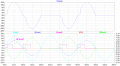
There is and input (control) and an expected output waveform (attached) and what I'm trying to achieve is a circuit that generates the output based on that input control signal. Can it get more well-defined than this?
If any question on those signals please feel free to ask. If you have any idea what circuit achieves that output feel free to share and I would be grateful as I'm not expert in this area and trying to connect the dots and learn bit by bit.
I'm only new here, so perhaps you need to tell me what's this forum about then. I thought it is about what the title says: "All About Circuits".
If it is all about circuits I have well defined the circuit that I'm after.
If it helps, let's say it's something hypothetical and an idea.
If you concerned about the load, it is not crystallized yet but most likely is going to be
12Vac RMS, under 1A RMS.
I didn't quite understand what you mean by "the time duration to operate the load".
I suppose none-stop free running.
If rather than 32VAC you can make your source 64VAC CT (add a 1:1 or 1:2 CT transformer?) then you always have both phases, i.e. both polarities of the sine wave available. Use one TRIAC on each phase, and around each zero cross fire the TRIAC that gets you the desired output polarity. Use optically isolated TRIAC drivers with built-in zero crossing detection, then your controlling micro can be a bit sloppy with detecting and acting on the zero crossing. (FWIW as a test I used an Arduino Nano to create 5 simultaneous channels of 8.33ms pulse density modulation, feeding zero-cross SSRs for incandescent lamp dimming purposes. The resulting flicker was HORRIBLE!)
make your source 64VAC CT (add a 1:1 or 1:2 CT transformer?) then you always have both phases, i.e. both polarities of the sine wave available. Use one TRIAC on each phase, and around each zero cross fire the TRIAC that gets you the desired output polarity.
Awesome man! That stuff worked!
I used MOC3020 for now which is not zero crossing because I didn't find MOC3041 that works.
I also realised my simulation had a problem with gate signal not attached to MT2. I think that's a must.
This is one possible solution, though it needs specific transformer.
I'm now moving to explore the H-Bridge idea MrChips mentioned, to see how that works.
One minor problem though is that I have a 7 volt drop across TRIAC which I wasn't expecting and that could be a show stopper.
1. Why is that? Is it just the particular TRIAC model (BTA16-600B attached) I'm using or is it typical.
2. What is the typical power consumption in TRIACs switching a 20W load at 32Vac.
3. Anyone has MOC3041 library that works? The one I have when running says didn't find "MyMisc.lib" and I don't find where in simulation it is referenced
Hi everyone
Here is a simple TRIAC example circuit showing voltage drop of 6V across TRIAC. Waveform and circuit files attached.
I think the 6v across TRIAC is exessive and with 1A current going through the load is 6W of dissipation.
What is acceptable and typical voltage drop across TRIACs?
What causes this voltage drop?
Any idea how to fix this so I get peak voltage at load as close as possible to peak voltage of source?
Here's an outline of one way of doing the polarity switching. I've deliberately simulated switching asynchronously with the AC as, for your intended purpose, I don't think switching the polarity at zero-crossings is critical. For synchronous switching the circuit would need more bells and whistles.
This is awesome Alec, good on you! I like the fact that all components can be SMD and price wise it's cheaper than TRIAC H-Bridge option. It does not have that strange voltage drop issue, too. Switching time is under 1us which is pretty fast. And I'm familiar with using similar MOSFETS.
I'm interested to look closer into this and related datasheet to understand it well and perhaps make a prototype to test.
A few questions for my understanding:
1. I plotted the waveform for HO and LO outputs of driver and LO looked like digital but HO was a half-rectified AC lookalike shape which I couldn't understand why it's like is that. Here is it below:
Is it just simulation or will I see that on real circuit too?
2. Depending on the answer for 1, if HO is supposed to digital, then do you think the function and timing of the IR2104 driver can be implemented in a firmware with digital outputs for HO (assuming HO is digital) and LO? What's particular about IR2104.
3. Any suggestion of parts/circuit for zero crossing detection that works close to zero point?
4. Any particular requirement on choice of MOSFETs if I wanted to replace with cheaper equivalents?
You should see it on a real-world circuit too, because the IR2104 driver IC boosts the gate voltage of the high-side FET to be 12V above the source voltage, and the source voltage gets pulled up close to the drain voltage, which is an AC half-wave.
The IR2104 is designed specifically for driving MOSFETs and IGBTs and can source/sink enough current to charge/discharge the gate capacitance quickly. This ensures the FET switches cleanly to avoid excessive heat generation.
Choice of FET depends mainly on how much current your load requires. There's a wide range available from the usual distributors. Take your pick. Can't suggest any particular FETs or zero-crossing detectors.
Here's an outline of one way of doing the polarity switching. I've deliberately simulated switching asynchronously with the AC as, for your intended purpose, I don't think switching the polarity at zero-crossings is critical. For synchronous switching the circuit would need more bells and whistles.
I'd like to appreciate your great help on this and had an offer as extension of my appreciation which I tried sending through private message to you, however, it failed. Could you please PM me your email or other contact to be in touch?
I appreciate it a lot.
Cheers,
Matt
Thanks Alec, yes as far as technical discussions go, for sure. I was getting in touch to send you a gift card that's why I tried PM. Please feel free to get back to me if you wish so.
 Facebook
 Google
 GitHub
 Linkedin