About simple T/R switch circuit

Thread Starter

demir-ali

Joined Jul 13, 2024
321
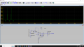
Hi, I thinked about if I can improve the transmitter stage of my project and decided to use darlington pair to deliver larger pulses to piezo directly.
As we do not want these signals to arrive to the receiver side , I designed this simple T/R switch. In theory , it seems like working with small leakage. I am not sure If does it actually work or if these leakages are actually is a problem and how to prevent if needed. I be very happy if you can review my circuit.
The sim works as followed :
1: Pulse is delivered to R1. SWITCH_BIAS is 0V.
2: As pulses delivered , SWITCH_BIAS goes 5v to open the path for small echo signal.
In part 2 , I connect ECHOSIGNAL1 to node E1 to simulate incoming echo signal.
1725225315860.png
 

Attachments

Last edited:

Thread Starter

demir-ali

Joined Jul 13, 2024
321
Sir , i did shared already,
To amplify 5V to bigger pulses , here's my new modified asc file but the first one is attached at the post
In practical experiment I figured out It does not work when I connect piezo in series but it works I connect piezo in parralel with that R1 through a capacitor
 

MisterBill2

Joined Jan 23, 2018
27,193
Consider that the piezo transducer is an open circuit for DC, after the capacitance charges. So it needs an alternative path for the current to bias the diodes on and off. Possibly a tuned circuit to present a high impedance at the transmit/ receive frequency while being a lower resistance for the diode bias charging, and forward current. Also, know that the bis voltage must be high enough to keep the diodes fully on and fully off.
One more thing is the kind of diodes: The diode symbols in post #5 are not the ones for 1N914 diodes.
 

Thread Starter

demir-ali

Joined Jul 13, 2024
321
Here is the results I get. I also upload the current circuit as asc file.
I also realized , eventhough this circuit is good for amplify square wave , it still requires impedance switch to be used in the application.
Using PPA might would solve this issue.
First : The voltage across the piezo
a.pngSecond : Voltage across diodes at node B.
B1.pngThird: Voltage at the output.
b.png
UPDATE:
I have biased the incoming signal to set a dc barrier and It worked. I reupload the file.
1725293457775.png
 

Attachments

Last edited:

ericgibbs

Joined Jan 29, 2010
21,395
hi demir,
This is your last asc file, slightly modified. note the 100k dummy load.
Note the IDeal diode, if you connect the E to the Echo without that diode the TX gate pulses are shunted to 0V.
Remember, an Ideal voltage source has a zero internal resistance.
E
BTW: don't keep using Draft1 as the file name, it gets confusing, use a short descriptive file nameEG57_ 2049.png
 

Attachments

Thread Starter

demir-ali

Joined Jul 13, 2024
321
hi demir,
This is your last asc file, slightly modified. note the 100k dummy load.
Note the IDeal diode, if you connect the E to the Echo without that diode the TX gate pulses are shunted to 0V.
Remember, an Ideal voltage source has a zero internal resistance.
E
BTW: don't keep using Draft1 as the file name, it gets confusing, use a short descriptive file nameView attachment 330800
Hi Eric , do you find this switching method true as It works like how we wanted ?
 

ericgibbs

Joined Jan 29, 2010
21,395
hi demir,
This is what I see when using a 40kHz Piezo model.
There is the typical ringing of a Piezo transducer that is always a problem, which effects the shortest distance measurement. [0.3mS through to 0.8 Msec after the TX pulses stop.

The usual method as I have posted earlier is that timed gain control is required, also a suppression period in which the Voutput is ignored by the detecting software after the TX pulses end.

Add to this asc file any further modifications are planning to use.
E
EG57_ 2052.png
 

Attachments

Thread Starter

demir-ali

Joined Jul 13, 2024
321
Hi , then I assume you find this switch method usefull. In this modification , I would liked to improve the tx stage and add the T/R switch. I haven't started to rebuilding the circuit yet. There is only 12 days left in my summer vacation and since I live in the school's dorm , I leave my equipments in house and can not practice experiments. Now I atleast do some small improvments and study electronics.
The piezo BVD model is usefull for me also thanks for it !
 

Thread Starter

demir-ali

Joined Jul 13, 2024
321
hi demir,
This is what I see when using a 40kHz Piezo model.
There is the typical ringing of a Piezo transducer that is always a problem, which effects the shortest distance measurement. [0.3mS through to 0.8 Msec after the TX pulses stop.

The usual method as I have posted earlier is that timed gain control is required, also a suppression period in which the Voutput is ignored by the detecting software after the TX pulses end.

Add to this asc file any further modifications are planning to use.
E
View attachment 330806
I also figured out , when we directly wire the piezo at begining it didn't work but now it works. I guess by T/R switching newtork , we created a path for DC too.
1725368962079.png
 
Top