75V power supply using a 555

RichardO

Joined May 4, 2013
2,270
cmartinez:
Several comments on your circuit...

For 75 volts at 100 ma, the output power is 7.5 watts. If we assume a conversion efficiency of 80% then the input power will be over 9 watts -- lets assume 10 watts for a safety margin. 10 watts at 12 volts is 0.833 amps. This is the average current that flows through the inductor. In this type of circuit, the peak current of the inductor is about 4 times the average current. This means that the inductor needs to be rated at more than 3.3 amps.

I would use a 4 to 5 amp inductor with a series resistance of less than 0.050 ohms. Expect this inductor will be large: something like 1/2 inch in diameter and an inch long. To get this current, the inductance has to be smaller in your circuit. I would use 33 uH.

The IRF740 MOS-FET has way to high an on resistance -- as much as 0.55 ohms. At 3.3 amps it will drop almost 2 volts!
You want a MOS-FET with a maximum on resistance of 0.050 ohms. You can use a MOS-FET with a drain-source breakdown voltage of less than the 400 volts of the IRF740. I would go for about 150 volts.

The connection of the potentiometer is wrong. When it is adjusted to one end the output voltage is unregulated and can go to hundreds if not thousands of volts destroying the MOS-FET. I would put a 1K resistor in series with the ground leg of the pot.

You need to use a fast rectifier diode. The UF4004 is a fast diode with a reverse recovery time of about 50 nS.
Do _not_ use a 1N4001 series diode because the reverse recovery time is much slower at about 2 uS.
(A 1N4148 switching diode is fast enough but will not withstand the high currents in the circuit).

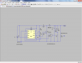
See my version of the circuit...
 

Attachments

ronv

Joined Nov 12, 2008
3,770
We should probably start over. Rich, your circuit has the wrong duty cycle. That is why the inductor has to be small in inductance and high in current.
So if we start with the calculator with 12v in and 85v out with a constant load of .1a, we need about 1Mh. It will now run in continuous mode at much lower current in both the inductor, transistor and diode.
 

Thread Starter

cmartinez

Joined Jan 17, 2007
8,768
Thank you all for your recommendations, and for taking the time to try to help me out here.

Ronv and RichardO, I've tested both of your circuits and I'm quite impressed at the amount of time and thought that you've put into them, thank you very much.

RichardO, yes I've been using the UF4004 from the beginning as you recommend, I mentioned that I tried to use the 1N4004 (only for simulation purposes) since I couldn't find the UF one in the database. And WOW! your circuit works perfectly (at least in theory, ha ha ha) I can see that current at the 1µh inductor peaks at 3A... is that the value I should use? Or could I use a lower value, since I'm guessing that the current's RMS through the inductor is much lower?. I didn't know I could substitute the BC547 for the much easier to find 2N3904, thanks for that too. I'm going to do some googleing around... see how I can make a 33µh inductor myself, since that's the only part of the circuit that don't have available. Also, how can I adjust the pot's value in your circuit?

I can see that you've both used different MOSFETs, and also that the Si4484EY is a much better choice than my IRF740, but I'm a little nervous about using the SI4484EY, since its datasheet says that it's rated at 100V (too close for comfort to 75V, in my opinion) and also, I see that the inrush current though it peaks at almost 100A when I simulate your circuit !!! Of course, that only lasts for about 1µs, from what I see, and then it quickly settles down to 5A pulses at 31Khz, with what a appears to be a duty cycle of 25%, and yes the Si4484EY has much lower resistance than the old IRF740
On the other hand, the FQU4N50's datasheet says that it has a D-S resistance of 2.7 ohms!!! that's far higher than the IRF740... so what I'm gonna do is test the circuit with the IRF740 anyway since that's what I have available at this moment.

Ronv, your circuit's giving me a 90V output instead of the 75V I'm looking for, would installing the resistors, pot and the 2N3904 allow me to adjust it?

Thanks again for your extremely valuable help!
 

Thread Starter

cmartinez

Joined Jan 17, 2007
8,768
Update... I finally found out how to adjust the pot in your circuit Rich, so don't bother on that one... your circuit works beautifully!
Ronvv, I tried to implement the changes you're suggesting in both Rich's circuit and yours, but I couldn't make it work properly... could you please elaborate?
 

wayneh

Joined Sep 9, 2010
18,108
Can we see a picture of the current schematic? I'm a bit lost. Might this design be capable of giving 120V at 100mA? Would the inductor cost be prohibitive?
 

Thread Starter

cmartinez

Joined Jan 17, 2007
8,768
How much current is going thru M1? I other words, what kind of efficiency does this reach?
I'm reading peaks of around -1.5A at M1, although I estimate that the RMS is around -0.7A
I get 75V at the output, although a little jagged, when I change the value of C2 from 1 µf to 4.7 µf the curve smooths out a bit, but the output jumps to around 85V
 

wayneh

Joined Sep 9, 2010
18,108
..I estimate that the RMS is around -0.7A...
YOU estimate? LTspice will do an RMS calculation for you - no need to estimate on your own.

0.7A at 75V doesn't concern you?

Sorry, I didn't mean to sound confrontational. I just re-read this and it could be heard that way. Not intended.
 

ronv

Joined Nov 12, 2008
3,770
Yes, It doesn't regulate very well. Let me take a look at another potential circuit that may be even simpler.
It is about 93% 7.84 watts in, 7.34 watts out. Most of it lost in the FET, and inductor.
PS with no load the voltage will go very high. Don't know if that's a problem for you or not.
Edit:
The .7 amps is from the +12 to initially get it up to voltage.
 

Thread Starter

cmartinez

Joined Jan 17, 2007
8,768
YOU estimate? LTspice will do an RMS calculation for you - no need to estimate on your own. 0.7A at 75V doesn't concern you?
Sorry, I didn't mean to sound confrontational. I just re-read this and it could be heard that way. Not intended.
Nah... you didn't sound confrontational... just a little excited... ha ha ha.
Anyway, I'm a newbie, a rookie and a probie on LTspice, and I downloaded and started learning it only yesterday night...
And yes 0.7A@75V is of some concern, but that's M1's output which I can protect from accidental contact, the circuit's output is 0.100 A
 

wayneh

Joined Sep 9, 2010
18,108
Interesting. A lot of commercial inverters for electroluminescent lighting carry a warning that they can be damaged by not loading them.
 

Thread Starter

cmartinez

Joined Jan 17, 2007
8,768
PS with no load the voltage will go very high. Don't know if that's a problem for you or not.
Well, yes... sometimes the circuit will be running with no load... would a high impedance resistor at the output prevent this? Say I replace the 750 ohms with a 100K ?
 

wayneh

Joined Sep 9, 2010
18,108
.. I'm a newbie, a rookie and a probie on LTspice, and I downloaded and started learning it only yesterday night...
It's pretty tough to get started, but you won't regret it. I just picked it up this summer and now I regret waiting so long.

Once you have a parameter plotted in you simulation, control-left-click on its name (for example "V006") in the chart header to get extra information including the integrated RMS value. That's for the Mac version, but if you hold your cursor over the name of the curve, it'll tell you the key combination you need to use. That's probably true on all versions.
 

Thread Starter

cmartinez

Joined Jan 17, 2007
8,768
It's pretty tough to get started, but you won't regret it. I just picked it up this summer and now I regret waiting so long
Hey! it worked!
I'm getting an RMS 0f 0.609 A at M1's output, so yes, I was a little way off the mark on that one... thanks for the tip...
 

Thread Starter

cmartinez

Joined Jan 17, 2007
8,768
Yes, It doesn't regulate very well. Let me take a look at another potential circuit that may be even simpler.
Question: what if I were to replace R1 and R2 with a 10K pot with its center tap connected to the DIS pin on the 555? you know, as a voltage divider...
Would that let me adjust the duty cycle, or would you not recommend it?
 

ronv

Joined Nov 12, 2008
3,770
Maybe 3 25 volt 5 watt zeners on the output to clamp the voltage at 75 volts?
We may be getting past this circuits possibilities.
 

wayneh

Joined Sep 9, 2010
18,108
I'm getting an RMS 0f 0.609 A at M1's output, so yes, I was a little way off the mark on that one... thanks for the tip...
I'd say you were darn close. Same conclusion either way, a LOT of power is being diverted to a waste. Do you see a similar current coming out of the 12V source? Actually, it should be a lot more because of the voltage ratio. (Power is conserved.)
 

Thread Starter

cmartinez

Joined Jan 17, 2007
8,768
I'd say you were darn close. Same conclusion either way, a LOT of power is being diverted to a waste. Do you see a similar current coming out of the 12V source? Actually, it should be a lot more because of the voltage ratio. (Power is conserved.)
Mmmhh... I'm getting a reading of 653 mA RMS on that... although the waveform jumps between 760 and 550 mA.. compared to the 100 mA RMS @ 75V, that would be 7.836 watts at the input and 7.5 watts at the output... which (if I'm not mistaken) would be an efficiency of 96%.... it's not that bad, is it?
 
Top