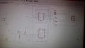
The relevant portion of the schematic:
You said 7447, but you have 7448 in the schematic. Which is it?
Your schematic would be easier to read if you arranged the components to minimize wire length and crossings. You are also missing current limit resistors for the display.
So it doesn't work. Tell us what it does and what it doesn't do.
Show us a photo of your breadboard.
If it is a pcb, show us photos of both sides of the pcb.
This is like sending an e-mail to a mechanic and telling them that your car "just doesn't work" and expecting them to tell you what's wrong.
What do you mean by "it just doesn't work"? It just might help the people you want to have help from if they knew whether "doesn't work" meant that it counted in the wrong order versus sitting there in a single state versus changing states erratically versus bursts into flames. It would also be nice to know if it just doesn't work in simulation versus on a breadboard versus on an actual pcb.
The relevant portion of the schematic: View attachment 122424
You said 7447, but you have 7448 in the schematic. Which is it?
Your schematic would be easier to read if you arranged the components to minimize wire length and crossings. You are also missing current limit resistors for the display.
This is like sending an e-mail to a mechanic and telling them that your car "just doesn't work" and expecting them to tell you what's wrong.
What do you mean by "it just doesn't work"? It just might help the people you want to have help from if they knew whether "doesn't work" meant that it counted in the wrong order versus sitting there in a single state versus changing states erratically versus bursts into flames. It would also be nice to know if it just doesn't work in simulation versus on a breadboard versus on an actual pcb.
When i use the push button its just turns into 2 and stop changing both in the pcb and the bread board i thought the schematic was wrong, I've put the right schematic in an other reply .
So it doesn't work. Tell us what it does and what it doesn't do.
Show us a photo of your breadboard.
If it is a pcb, show us photos of both sides of the pcb.
I dont have the pcb right now but when i use the push button to go up it turns into 2 and stop changing it doesn't even start with zero. I thougt i made a wrong schematic .
So it doesn't work. Tell us what it does and what it doesn't do.
Show us a photo of your breadboard.
If it is a pcb, show us photos of both sides of the pcb.
When wiring a 7-segment display to a 7-segment decoder-driver here is a first simple test you should always do.
Temporarily connect LAMP TEST, pin-3 of 7446/7447/7448 to GND.
All seven segments should light up and display the numeral 8.
After doing the test, return pin-3 to Vcc.
Without debouncing the switches, the counter can change dozens of counts with each press, depending on the construction of the switches. Also, you need decoupling capacitors for each chip.
1. I've redrawn your schematic for clarity, added debounce for the switches, ballast for the display segments, and a POR (power-on-reset) so the counter will come up on either 9 or 0. Maybe...
2. If you're using a 74LS47 for the display driver, the display must be common anode, and the anode must go
to +5 volts. You show it going to ground.
3. I've not shown it, but U1 AND U2'S unused inputs should be connected to either +5V or ground.
The latest schematic follows, and I've changed the up-down clock controls to make the 74192 happy, the POR to drive the counter's CLEAR input successfully, and the pushbutton switch interface in order to address Scott Wang's and MrChips' concerns.
When i use the push button its just turns into 2 and stop changing both in the pcb and the bread board i thought the schematic was wrong, I've put the right schematic in an other reply .
Here are excerpts from the TI and ON semi 'LS 192 data sheets. Note that if you want to count UP, the DOWN input must be held high while the UP input is pulsed, and if you want to count DOWN, the UP pulse must be held high while the DOWN input is pulsed.
1. I've redrawn your schematic for clarity, added debounce for the switches, ballast for the display segments, and a POR (power-on-reset) so the counter will come up on either 9 or 0. Maybe...
2. If you're using a 74LS47 for the display driver, the display must be common anode, and the anode must go
to +5 volts. You show it going to ground.
3. I've not shown it, but U1 AND U2'S unused inputs should be connected to either +5V or ground.
The latest schematic follows, and I've changed the up-down clock controls to make the 74192 happy and the POR to drive the counter's CLEAR input successfully. View attachment 122630
The low level for 74LSxx that the pull low resistor should be around 330Ω, if the pull low resistor too big then the input level will not reach to a stand low level, because the internal resistor and pull low resistor as a voltage divider, you can check the internal circuit of 74LSxx series ic.
The low level for 74LSxx that the pull low resistor should be around 330Ω, if the pull low resistor too big then the input level will not reach to a stand low level, because the internal resistor and pull low resistor as a voltage divider, you can check the internal circuit of 74LSxx series ic.
 Facebook
 Google
 GitHub
 Linkedin
 25.3 KB Views: 31