 Facebook
 Google
 GitHub
 Linkedin
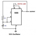
555 voltage booster
- Thread starter Wendy
- Start date


| Thread starter | Similar threads | Forum | Replies | Date |
|---|---|---|---|---|
| H | power supply voltage booster | Power Electronics | 15 | |
| J | MOSFET voltage booster heat and protection | General Electronics Chat | 10 | |
| A | Voltage Booster | Power Electronics | 37 | |
| B | The Induction Coil of DC Voltage Booster. | Power Electronics | 7 | |
| T | DC voltage booster not working as expected? | Power Electronics | 17 |


