A PICAXE microcontroller is simply a PIC microcontroller with a bootloader already programmed. You can use an 8 pin PIC instead, but you will have to program it in assembler, C, basic, or something else. Look at the datasheet for PIC12F629.
Ok..thx~ by the way, back to the original plan by using the 555 timer. I have one question to ask. What's the diff of using NE555 and 7555? I know that the latter is the CMOS version of 555. So lets say, I'm short of 1 NE555, can i use 7555 to replace the last one? Or i change all 4 NE555 to 7555? Will this change the circuit?
Sorry I'm here again. From the pdf file, at every component, there is 1 &2. does that mean posiitive & negative?
I tried to transfer the circuit diagram to stripboard using Lochmaster, however, I stuck from the very beginning where I need to select the board layout. & from the list of components, I am not able to find the timer component. Why?
Is there any software where I can automatically transfer the circuit diagram to stripboard? Sorry that I asked this because I do not know how to connect from point to point. I have only done soldering by refering circuit diagram from hobby kit where the board had already shown the holes where we need to insert the components & straight away soldering.
The small numbers on the schematic are just pin numbers and don't serve any purpose other than identification of the pins. They don't mean positive or negative.
I don't know anything about stripboard software, so I can't help there.
The quad timer circuit is quite an ambitious assembly project for someone with little experience. Are you a student, and if so, at what educational level in electronics?
ya, i'm a student from malaysia. The stripboard i have with me is kinda golden brown with strips, and the other face is dull green.
Power source? I'm using battery.
i had tried expresssch. but the software does not convert onto the board.
one more ques, hw to calculate the time obtain from the file by tracecom?
U1-U4?
10 mins: 1.1 x 510kΩ x 1000µF = 561 secs ≃ 9.35 mins
15 mins: 1.1 x 390kΩ x 1000µF = 429 secs ≃ 7.15 mins ( but 14.3 mins is shown) Is it times2? How?
20 mins: 1.1 x 510kΩ x 1000µF = 561 secs ≃ 9.35 mins ( but 18.7 mins is shown)
30 mins: 1.1 x 820kΩ x 1000µF = 902 secs ≃ 15.03 mins ( but 30.1 mins is shown)
There are two mistakes. One is my mistake in putting only one 1000μF capacitor in the timing circuit for U2; there should be two for a total capacitance of 2000μF. The other mistake is that you overlooked the second 1000μF capacitors in the timing circuits for U3 and U4. So, U2, U3, and U4 each should have two 1000μF capacitors in the timing circuit. U1 should have only one.
I used all 1000μF capacitors in order to reduce the number of different value components required.
ETA: A corrected schematic is attached with C16 added to the timing circuit for U2.
Tolerances on large caps can be quite loose, -10% to + 20% or more, so it might be well to use a variable resistor [ pot ] of 1meg to set timing, measure & replace with closest available value, on each timer.
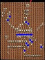
This is my first experience with stripboard, Laid out on 1/4 in grid. As OP's componet sizes are unknown , just used what I had & only covers U1 & U2. Horizontal lines are jumpers, X = hole drillid with 3 mm bit to break trace. Accuracy not guaranteed as it's only a suggestion of how to proceed.
What a transformation. Only problem I see is that SW's are shorted, not too clear on origional, wide spaced pins are common on ea side.
Gumbo is with chicken & ham- should have used rattlesnake or gilla monster.
Pin 6 and pin 7 are physically connected, so they are electrically the same node. R1 should be electrically connected from 9V to that node, but it does not matter whether R1 is physically connected to pin 6 or pin 7.
 Facebook
 Google
 GitHub
 Linkedin