Facebook
 Google
 GitHub
 Linkedin
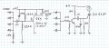
thx..hmm, can you plz draw the circuit for both esp the one with 4 555 timers.C1 is a noise suppression capacitor that actually plays no role in the timing. R1 is a pullup resistor to hold the reset pin and the trigger pin high until SW1 is pushed. The timing is controlled by C2 and the choice of R2, R3, R4, or R5.
In operation, the user operates a switch to select either R2, R3, R4, or R5 depending upon how long a delay desired, and then presses SW1 to start the timer. If you would be satisfied with that operation, then this would be a solution for you. I will be happy to calcutate the appropriate values for the resistors and capacitor if you want to use this.
If you must have a separate pushbutton for each of the times you want, then I think that a separate 555 circuit for each time is the simplest choice. That would mean four similar 555 circuits, one for each of the four times you want. If that is what you want, I will draw a diagram and post it.
Just say which solution you want and the times. Don't forget that the times won't be exact because of the tolerance in components and the effects of temperature and aging.
For the timing, since I'm nt sure why 470µF is used. So i continue using the same value to obtain the timing. (Or maybe I shld chg the value of capacitor?)
10 mins: 1.1 x 1.1MΩ x 470µF = 568 secs ≃ 9.48 mins
15 mins: 1.1 x 1.6MΩ x 470µF = 827.2 secs ≃ 13.78 mins
20 mins: 1.1 x 2.2MΩ x 470µF = 1137.4 secs ≃ 18.96 mins
30 mins: 1.1 x 3.3MΩ x 470µF = 1706.1 secs ≃ 28.44 mins
What do you think?
")