50% duty cycle in Idle

Thread Starter

Motanache

Joined Mar 2, 2015
652


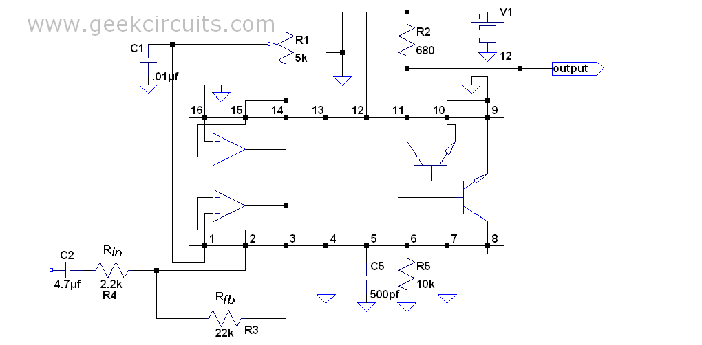
Duty cycle in Idle 50% is set from R1.

Continuous output voltage is set from R1.
In practice I have to always set from R1 and I do not understand why.


I'm looking for a method to be no risk of having DC through the loudspeaker.

Obviously I can put a capacitor in series with the speacker but I do not want this option.
The signal from pin 3 of the IC is compared with a sawtooth(from C5,R6)
 

Thread Starter

Motanache

Joined Mar 2, 2015
652
You need a capacitor unless you operate the circuit from ±6V supplies.
The speaker is 15" and I have symmetrical voltage source +40v GND -40V
Also has a MOSFET driver (IR2110) but has no feedback from output.

The capacitor becomes very large and expensive and it limits low frequencies.
 

Thread Starter

Motanache

Joined Mar 2, 2015
652
The best "version" to not have DC through the loudspeaker is the capacitor in series.

But I'm looking for the version without this capacitor. This in two cases:
-Symmetric power supply
- Simple power supply and H bridge. That means two extra transistors..

Anyway if I did not have a 50% duty cycle in Idele it is not good.

The provisional solution I'm thinking about - Measure if I have DC on the speaker and it brought an error signal to stop the circuit

=================================================================================
I posted here to find another configuration of error amplifiers in TL494 (post #1):

Pin 14 is Vref, the reference voltage. The saw tooth signal is between GND and Vref(5V).
Potentiometer R1 has the cursor somewhere halfway(2.5V) from GND to Vref voltage.

This voltage reaches pin 1 which is the noninverting input in the operational amplifier.
(The other one operational amplifier is not used)
 
Last edited:

Thread Starter

Motanache

Joined Mar 2, 2015
652
This operational amplifier is in inverting configuration.

Practically without an input signal the output of this operational amplifier will be at the +IN potential (2.5V).

This OA output voltage is compared to the sawtooth(0...5V) and get a PWM with a duty cycle of about 50%.

Just this rule is not very good, and 2.5V in pin 3 is not exactly 50% PWM.
It gives me a DC on output high enough to ruin something (at +/-40V on power MOSFETs)


===========================================================
Now my idea:
Let's make the potential of pin 1 (+ IN) change depending on the DC through the loudspeaker.
OR:
Let's get the speaker's "GND information" to reach to pin 1
 
Last edited:
Top