555 timer with adjustable duty cycle

Alec_t

Joined Sep 17, 2013
15,112
Please post the schematics for the two circuits, with designators for all components, so that we can see and discuss them.
 

crutschow

Joined Mar 14, 2008
38,423
there is only a few components and you need a schematic for that?
Yup.
Schematics is the language of electronics, not pictures of PCBs or verbal descriptions.
We would have to draw the schematic from your PCB and that's not generally part of the free work we do here.

Are you telling us the circuit was built without a schematic?
 

Thread Starter

Jopee

Joined Jun 30, 2024
41
Yup.
Schematics is the language of electronics, not pictures of PCBs or verbal descriptions.
We would have to draw the schematic from your PCB and that's not generally part of the free work we do here.

Are you telling us the circuit was built without a schematic?
That is from a youtube video by "The Engineering Mindset". Oscilloscope guide.
 

ulms

Joined Mar 19, 2024
179
Looks like you garnered the wrath of the cranky crew. A picture like that works well enough and is quite clear and straight forward especially for experienced and very talented guys like the above members.
 

sghioto

Joined Dec 31, 2017
8,634
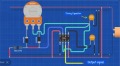
Can someone explain why the circuit without diodes doesn't work? It still has different paths for the capacitor to charge and discharge. Charging uses left side of the potentiometer and discharging uses right side.
As configured from the image in post #1 seen below, it does work without the diodes to some extent.
100% to appx 30% duty cycle over a short span of the pot.
Then goes to zero output on the remaining travel which is more then 1/2 the total rotation.
Verified on a breadboard.
1767496456648.png
 
Last edited:

crutschow

Joined Mar 14, 2008
38,423
A picture like that works well enough and is quite clear and straight forward especially for experienced and very talented guys like the above members.
You forgot lazy.
I'm not interested in doing the work of drawing a schematic from a layout (although sghioto apparently is :)) .
That's the TS's job.
 
Last edited by a moderator:

Thread Starter

Jopee

Joined Jun 30, 2024
41
As configured from the image in post #1 seen below, it does work without the diodes to some extent.
100% to appx 30% duty cycle over a short span of the pot.
Then goes to zero output on the remaining travel which is more then 1/2 the total rotation.
Verified on a breadboard.
View attachment 361577
Thanks. I just don't understand why it doesn't work properly.
 

crutschow

Joined Mar 14, 2008
38,423
Yes. Like it works with the diodes.
Why would you expect it to work the same with or without diodes?
The diodes isolate the charge resistance from the discharge resistance so that the two can independently control their respective times.
Without the diodes, the two resistances interact such that the full duty-cycle range cannot be achieved.
 
Top