Facebook
 Google
 GitHub
 Linkedin
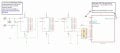
I am attempting to design an adjustable time delay circuit that will energize a relay after an adjustable delay of 1 to 5 minutes. It will be used in a control system that uses 24 VAC power, which is a standard in the heating and cooling industries.
My rough parts list looks like this:
(a) An LM555 timer and associated RC components. The timer has to be latching, with two LEDs - one to indicate initiation of the countdown window and one to indicate the latched alarm condition at the end of the countdown window. A momentary push button will reset the timer.
(b) Qty 3 (or maybe 4) power relays, PCB type, Omron G2R-2DC12 or equal, with diodes. The relays are needed to connect to the real world building controls. Each relay coil is rated at approximately 0.52 W. At least one of the relays will have 24 VAC coil from an external source.
(c) A power supply circuit to get to 12 VDC for the rest of the circuit. I am having trouble sourcing a PCB step down power transformer and I have no experience in the design of a step down circuit using an IC. I tried to use the TI design tool for the LM2596 without success.
(d) A PCB for all the above, with thru hole wiring terminal blocks. Also required for real world interface.
(e) A DIN rail mounted case to house the PCB and mount the PB and LEDs.
I have bread boarded the timer circuit with an adjustable potentiometer. However, that approach will not be acceptable in the field because it takes too much time to set the pot and time the result. So I am thinking that I could replace pot with a dip switch and fixed resistors. The circuit would have to be able to set the time from one minute to five minutes in approximately 30 second steps. The accuracy would have to within + or - 5 seconds for the DIP switch to be acceptable.
Any advice on this approach would be appreciated.