4017 counter signal to toggle between two PWM signals

danadak

Joined Mar 10, 2018
4,057
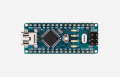
Here is an approach using block language programming and an Arduino Nano board (~ $3).

The middle window is where you drag programming blocks to and configure. As shown
the block code stays at a given servo angle for 5 secs, that can be changed to pretty
much anything you want.

mBlock then converts that to Arduino code (shown in right hand window) and programs
board. Lots of fun. Kids are using it to program simple robots.

There are other block languages, like Snap4Arduino, that can even do things like a
talking voltmeter of freq meter or whatever, with board tethered to PC. Simple block
programming.

Looking at middle window the first block tells the Arduino to start running code on
powerup. The next block, "forever", tells Arduino to run over and over forever the
code between its arms. Next block sets the servo angle, then a 5 sec wait whicl at that
angle is done. Then angle changed and again that is held for 5 secs. And run that se-
quence over and over. Note if you needed button control thats easy to add.


1575204692418.png

mBlock is free.

Arduino Nano board -

1575205272909.png


Regards, Dana.
 
Last edited:

ElectricSpidey

Joined Dec 2, 2017
3,356
I have an alternative low power solution if you are interested, since you mentioned batteries.

In my alternative only the sensor needs constant power.

Also when using the PIR with the current circuit, you will need a capacitor in series with the output, so the base of Q1 returns to positive. (if the output is longer than the cycle)
 

crutschow

Joined Mar 14, 2008
38,682
I meant that the circuit doesn't react on the NAND gate but now I know it was because it has to stay high. I mixed it up with the function of a mosfet.
An N-MOSFET in that circuit, would act essentially the same as the NPN BJT.
Why do you think it would be different?
I think I have to switch the IC's around because the second 555 timer runs all the time. I should make sure they dont use up the battery when its not necessary.
The standard 555's will actually take more power when the RST pin is low, because the puts the DIS pin in the low state also, where it will then constantly draws max current from the timing resistors connected to Vdd.

For minimum power you could use the CMOS version of the 555 (LMC555) which takes only about 0.1mA of current.
If you do that, than you could increase the values of all the timing resistors (R1 through R5) by a factor of 10, and reduce the timing capacitors (C2 and C4) by the same factor, to further minimize the current draw.
 

ElectricSpidey

Joined Dec 2, 2017
3,356
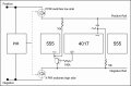
Only the mods are shown in the diagram, and is based on the circuit sans the NAND.

The PIR must output long enough to complete one cycle.

Basically the PIR turns on the MOSFET applying power to the circuit, the Cap on the 4017 reset insures it starts at Q0, when the 4017 reaches Q9 it turns on the NPN which in turn resets the 555 stopping the cycle.

The MOSFET is chosen depending on whether the PIR switches high or low side, the other rail is then connected directly. Choose a logic level MOSFET.

You can also choose either MOSFET right from the beginning and simply invert the PIR output if needed. (one more transistor)

It’s a simple mod, and can be tested by simply connecting power. (without the PIR)

A_Servo_Alt.jpg
 

Thread Starter

christiannielsen

Joined Jun 30, 2019
389
An N-MOSFET in that circuit, would act essentially the same as the NPN BJT.
Why do you think it would be different?
The standard 555's will actually take more power when the RST pin is low, because the puts the DIS pin in the low state also, where it will then constantly draws max current from the timing resistors connected to Vdd.

For minimum power you could use the CMOS version of the 555 (LMC555) which takes only about 0.1mA of current.
If you do that, than you could increase the values of all the timing resistors (R1 through R5) by a factor of 10, and reduce the timing capacitors (C2 and C4) by the same factor, to further minimize the current draw.
I dont know what a N-mosfet is. But I have a mosfet that stays high when gate gets a high pulse and stays high until gate gets a low pulse.


I have been working on this circuit all day and it all got worse and worse. I have removed the 4017 counter because I wasnt able to make the circuit stop after one cycle. The infrared sensor I used was high in idle mode which didn't go with the NAND gate. I also had trouble with the second 555 timer (PWM signal) which suddenly didn't position the servo horns correctly anymore. Have no idea why but it was after I removed the 4017 from the circuit. Lots of trouble. Sometimes it seemed that I couldnt even make a transistor work as a switch. It just didn't turn on. And if it did it didn't turn on completely. I also had trouble getting a transistor to power up all IC's and then and then and then. One problem led to another all day long.
 

Thread Starter

christiannielsen

Joined Jun 30, 2019
389
Only the mods are shown in the diagram, and is based on the circuit sans the NAND.

The PIR must output long enough to complete one cycle.

Basically the PIR turns on the MOSFET applying power to the circuit, the Cap on the 4017 reset insures it starts at Q0, when the 4017 reaches Q9 it turns on the NPN which in turn resets the 555 stopping the cycle.

The MOSFET is chosen depending on whether the PIR switches high or low side, the other rail is then connected directly. Choose a logic level MOSFET.

You can also choose either MOSFET right from the beginning and simply invert the PIR output if needed. (one more transistor)

It’s a simple mod, and can be tested by simply connecting power. (without the PIR)

View attachment 193531
I have never found out what a logic levet mosfet is and dont know what to search for. But I might actually have one, I just dont know what to look for.

The IR sensor only outputs 3 volt. Although it sometimes seems to output more. I would love to just use a IR LED and IR receiver but again: I have tried several circuits on how to make it trigger and what to trigger and how to make it latch (until 4017 tells not to anymore). Its really complicated I think. I jumped from one diagram to another when I bumped into obstacles. I think this project was a bit to difficult for me to understand. What really frustrates me is that I had 3 ic's working individually. But when I wanted to combine them all it all just got screwed up.
 

Thread Starter

christiannielsen

Joined Jun 30, 2019
389
I might try again tomorrow with another 555 timer in bistable mode to start and end the cycle by starting the cycle with a pulse from IR sensor to trigger pin and end with a low pulse from to the reset pin. But this has to be a low signal and the 4017 delivers only high signals. No one said this was easy.
 

Thread Starter

christiannielsen

Joined Jun 30, 2019
389
I might try again tomorrow with another 555 timer in bistable mode to start and end the cycle.
Only the mods are shown in the diagram, and is based on the circuit sans the NAND.

The PIR must output long enough to complete one cycle.

Basically the PIR turns on the MOSFET applying power to the circuit, the Cap on the 4017 reset insures it starts at Q0, when the 4017 reaches Q9 it turns on the NPN which in turn resets the 555 stopping the cycle.

The MOSFET is chosen depending on whether the PIR switches high or low side, the other rail is then connected directly. Choose a logic level MOSFET.

You can also choose either MOSFET right from the beginning and simply invert the PIR output if needed. (one more transistor)

It’s a simple mod, and can be tested by simply connecting power. (without the PIR)

View attachment 193531
thank you for trying to make me understand. how do you come up with the values of the resistors?

I've run dead in switching components all the time. And I dont have that many mosfets. I have IRLZ44N, IRF234N, IRL540N, IRL530N AND IRL520N
 

crutschow

Joined Mar 14, 2008
38,682
I dont know what a N-mosfet is.
There are two types of MOSFETs, N-channel which operate with a positive drain-source voltage, and P-channel, which operate with a negative drain-source voltage..
But I have a mosfet that stays high when gate gets a high pulse and stays high until gate gets a low pulse.
That's only if you leave the gate open, which stores that last gate input voltage on the gate-capacitance.
Eventually that voltage will leak off.
I have removed the 4017 counter because I wasnt able to make the circuit stop after one cycle.
Confused again.
In post #39 you say it works.

It obviously won't work if you remove the 4017.
Why would you think it would?

If you are going to randomly change the circuit without understanding what you are doing, then I can't help you any further. :confused:
 

Thread Starter

christiannielsen

Joined Jun 30, 2019
389
So it actually works, only the IR only outputs when it detects movement so the circuit will run continuously.
The NAND gate you provided me did work. But it dint work with IR sensor because its high in idle mode and low in action. So the sequence ran continuously.

Of course I didnt think it would work as I wanted without the 4017. But I wasn't able to make the 4017 end the sequence because of the already stated problem. When I tried to find solutions to it other problems occurred as described. Its out of my capability so I wanted to simplify the project. And that is why the 4017 went.
 

Thread Starter

christiannielsen

Joined Jun 30, 2019
389
There are two types of MOSFETs, N-channel which operate with a positive drain-source voltage, and P-channel, which operate with a negative drain-source voltage..
That's only if you leave the gate open, which stores that last gate input voltage on the gate-capacitance.
Eventually that voltage will leak off.
Confused again.
In post #39 you say it works.

It obviously won't work if you remove the 4017.
Why would you think it would?

If you are going to randomly change the circuit without understanding what you are doing, then I can't help you any further. :confused:
When I try to find solutions I wouldn't call it random. I am trying to fix the obstacles I meet. What you suggested didn't go with the IR sensor. And obviously the NAND gate went as well as it was designed in combination with the 4017.
 

Thread Starter

christiannielsen

Joined Jun 30, 2019
389
Then add a transistor inverter to invert the signal from the sensor.

The 4017 is needed to generate the two different signals for the servo.

You need to understand how the circuit works before you make arbitrary changes.
I know what the 4017 did. I put it together.
I can skip the 5 count and simply run it for a certain time of seconds.

Granted, as I wrote, I think this project was too big for me at this point although the 3 IC's worked fine both individually and combined before I wanted to put in sensor and nand gate to start and end the sequence.
For example I wouldn't know how to make a NAND gate from two resistors so thank you for that. I also dont know how to make a transistor inverter nor how to connect it to your NAND gate or IR sensor (time low can't be adjusted on the sensor).
 

crutschow

Joined Mar 14, 2008
38,682
Removing the 4017 wasn't a arbitrary change. As I wrote: I wanted to simplify the project because it was too big for me.
To paraphrase Einstein, "Make it as simple as possible, but no simpler".
You exceeded that dictum.
It is so simple that it won't work. :)
 
Last edited:

Thread Starter

christiannielsen

Joined Jun 30, 2019
389

I wanted to try to add another 555 timer in bistable mode to replace your nand gate as I wasn't able to understand how it worked and to make it work combined with my IR sensor. The result is in the video. This 555 timer now works as a latching switch by grounding trigger to start and reset to end. The IR sensor takes care of the trigger and the output 9 on 4017 takes care of reset. And this seems to work fine.

I now have two new problems.

The other IC's are running constantly. Do anyone have an idea to come around that? I was hoping a transistor was able to supply power to two or all other IC's but it doesn't look like it when I try. What is normal to do in this case? Is it normal to block off power to the IC's or?

As showed in the video when the servo motor is connected to the PWM signal it makes so much noise in the circuit that it switches on the first 555 timer in bistable mode which should only be switched on by the IR sensor. I am showing it in the video. Can anyone point me in the direction of what to look into?

I am aware that a diagram is needed for you to come up with precise solutions and I do understand you are very keen about the circuit diagram but I must do with only a point of direction if you have any suggestions.
 

ElectricSpidey

Joined Dec 2, 2017
3,356
Do you have decoupling caps at the 555?

You can also try and pull the trigger up a little to avoid false triggering, and be sure to have good filtering on the circuit as a whole.

I don't see any filtration on that BB.

Flyback diode on the servo might help as well.
 
Last edited:

Thread Starter

christiannielsen

Joined Jun 30, 2019
389
Thank you so much.

I know what a flyback diode is, I will try that.
I think I know what a decoupling capacitor is. Its "just" a capacitor between vcc and ground close to the 555 timer right?

Unfortunately I dont know what you mean by filtration and how it is done.
And I also dont know how to pull up the trigger at which timer.

This weekend I will try to use a couple of hours on diptrace so that I hopefully will be able to draw a diagram. It might also be needed to help me design the PCB. Otherwise Im not sure how the PCB will end up and if it will. :)
 

ElectricSpidey

Joined Dec 2, 2017
3,356
Correct
Correct

Filtration in this case simply means to place a cap, say 10 to 100uf on the power rails to help keep the voltage smooth.

Forget what I said about the pulling up the trigger for now.
 

Thread Starter

christiannielsen

Joined Jun 30, 2019
389
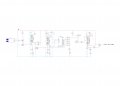
Here is a schematic I drew in diptrace. That was hard. I guess it shows.

Circuit.jpg

I am sure you can easily pin out mistakes and you are more than welcome.

When the schematic is as its suppose to, I have several issues about the circuit:

1. If the servo motor signal isn't connected to the circuit the circuit runs as supposed to. But when signal is connected to Q4, U1 is triggered constantly by noise (I think). I need help to place noice reduction.

2. After I replaced all 555 timere from NE555 to ICM7555 the U1 gets so hot that it almost starts to smoke. I might have to replace D1 with more resistance or what makes the difference between ne555 and 7555?

3. The servo motor won't run if D10 is connected.

4. D8 never stops lighting completely. There is still some light in it when not supposed to.

5. I need to find a way to make U1 power on and off all the other IC's so it won't drain the battery.
 
Top