Facebook
 Google
 GitHub
 Linkedin
MisterBill2
- Joined Jan 23, 2018
- 27,870
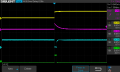
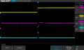
It certainly looks to me like the latch and reset pulses will be within a very few NANOSeconds of each other. so of course it will not work. the reset must not start until after the latch command has terminated. That is because the CD4042 is a STATE controlled device, not an edge triggered device. So the latch pulse must end before the reset pulse starts.
READING AND UNDERSTANDING the description of how the IC actually functions is often rather useful.
READING AND UNDERSTANDING the description of how the IC actually functions is often rather useful.