Facebook
 Google
 GitHub
 Linkedin
Hi
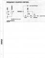
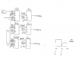
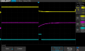
Here is a frequency counter circuit that I breadboarded. The circuit started out as a 0 to 999
counter. I modified it to measure an externally generated 100 Hz signal but the display only
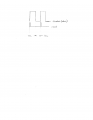
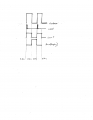
shows a zero. I have attached a schematic as well as a scope image of the control circuit.
Channel 1 is the timebase and channel to is the STORE signal. Not sure what the problem is.
Thanks
Here is a frequency counter circuit that I breadboarded. The circuit started out as a 0 to 999
counter. I modified it to measure an externally generated 100 Hz signal but the display only
shows a zero. I have attached a schematic as well as a scope image of the control circuit.
Channel 1 is the timebase and channel to is the STORE signal. Not sure what the problem is.
Thanks
Attachments
-
 61.6 KB Views: 34
 -
 19 KB Views: 32