Facebook
 Google
 GitHub
 Linkedin
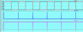
Here is a screen shot of the control signals.As a first step, remove the RESET control signal going into the counter. Set the RESET input to the counter to the inactive state.
Then look at the RESET signal on the oscilloscope with a zoomed-in view and compare the timing with the other important control signals. Look to see if there is any overlap with other control signals.
Channel 1 is the timebase and channel 2 is the RESET signal. To me it looks like the positive edge of the
timebase and the RESET overlap but I don't know how to use the scope to detect that.
Attachments
-
 19 KB Views: 3