25 amp motor controller help

SgtWookie

Joined Jul 17, 2007
22,230
Now that's going to be pretty darn cool. :cool:

OK, it's no wonder you're seeing lots of noise. Looks like you're running digital signals without using ribbon cable, or twisted (shielded) pair with differential transceivers. You are suffering from the dreaded "crosstalk". The signals on adjacent wires are being inductively coupled, so everything has boatloads of noise on it. This is a an unhappy situation, as you will have a good bit of re-thinking to do.

If your runs are short, you might be able to get by using multi-conductor flat ribbon cable, alternating ground-signal-ground-signal-etc. If your runs are more than a foot or so, you're going to have to go to twisted pair and transceivers on either end of the cabling.

Unless they are low-speed signals.

For power/ground, you need heavy gauge wire.

[eta]
It would help to have a complete schematic of your system, and you will need to note which are the high-speed digital lines.
 
Last edited:

Thread Starter

RobbJohnson

Joined Dec 15, 2009
76
As you can see from picture #1, I decided it was time to clean up and shorten leads. This was the first step in redesign per your sugestions.

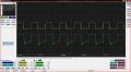
Picture #2 shows the input to the driver yellow trace and the gate of the mosfet under load of the original engine about 2 amps. Seems to work fine llike old circuit. Now, i will again look at a bigger motor, found a 100watt (max 6amps) and a 250 watt
ax 11amps) one of these should have plenty of torq (I hope). The two motors I amd using now are about two amps near as i can tell the tank moves but not as well as i would like.

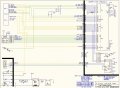
The next post will include an overall schetamic and a pic of the Windows software I use to monitor the systems.

If I can get past the chassis the upper boty may include a paint gun. The ultimate goal is to make the tank as atonomus as possible.

Thanks for all the information and help you have provided, I am doing this on my own, and you input is apreaciated.
 

Attachments

jpanhalt

Joined Jan 18, 2008
11,087
Are you using an air frequency for a ground vehicle? That is not a good idea.

I love the rest of the implementation. A few years ago , I came across a guy who has made a scale, operating D3 bulldozer. I think it was 1/4 scale-- quite large. He was a retired machinist, and he had made everything, including the tracks. It looks like you are well on your way to a similar feat.

John
 

SgtWookie

Joined Jul 17, 2007
22,230
As you can see from picture #1, I decided it was time to clean up and shorten leads. This was the first step in redesign per your suggestions.
OK, cleaning up the harness is a good start. But don't forget you really need to leave a bit of a "service loop"; that is so if you have to trim a bit off a wire later, you don't wind up being too short. The big thing here is to separate what is high-speed digital from what is low speed digital (just on/off controls).

Also, the power cables to the motor - keep them away from the other cables. Don't connect them in to the power bus you're using for the digital side. There's going to be a terrific amount of noise on them. Your supply for the digital side will need to be heavily filtered to remove the noise.

Picture #2 shows the input to the driver yellow trace and the gate of the mosfet under load of the original engine about 2 amps. Seems to work fine llike old circuit. Now, i will again look at a bigger motor, found a 100watt (max 6amps) and a 250 watt max 11amps) one of these should have plenty of torque (I hope). The two motors I am using now are about two amps near as i can tell the tank moves but not as well as i would like.
OK, I can't tell where the ground reference is on the MOSFET gate. It doesn't look like it's swinging 12v; it appears you have it set for 5v/div. The "off" state of the MOSFET gate has a good bit of ringing on it.
Are you referencing from the source terminal of the MOSFET to the gate, or from some other ground? The MOSFET source terminal is where the ground reference needs to be when measuring the gate voltage, and it should be adjusted on your scope to be 0v.

The next post will include an overall schematic and a pic of the Windows software I use to monitor the systems.

If I can get past the chassis the upper body may include a paint gun. The ultimate goal is to make the tank as autonomous as possible.
The turret? That'll be fun ;)
 

SgtWookie

Joined Jul 17, 2007
22,230
these are the other pictures
OK, now we're getting somewhere!

R/L engine current - from Rsense? (current sense resistor) - if so, limit current on the wire, reduce 10uF caps. The current limiting resistor needs to be as close as possible to Rsense.

That is likely how your uC got killed - trying to measure current right from Rsense without current limiting along with the filtering. But, need to see more of the schematic.

Engine temp - digital or analog?
 
I'm following this to get an idea for how I'd like to set up a controller I'm working on for an electric skateboard. I'd like to run my brushed DC motor at 36 V and 30 amps. It's a 1200 watt electric lawnmower motor. It will be unipolar, no need for reverse. I want to incorporate your idea Wookie, adding a low side power mosfet instead of a flyback diode in order to recapture energy and use it to extend battery power. I wonder, if running at a 50% duty cycle, how much energy can be recaptured by the 2nd mosfet? There's alot of schematics out on the web for this but not exactly what I need, for example MIT has a nice EV circuit for 36VDC controller but I do not need a programmable PIC any PWM driver will do to keep it somewhat simple. If I add a capacitor bank charged by the 2nd mosfet then how big should it be? This would be for a quick boost or to charge the battery.
 

SgtWookie

Joined Jul 17, 2007
22,230
Trismagistus,
While your inquiry is somewhat related to RobbJohnson's thread, it is going off at quite a tangent. This is what is called "hijacking" a thread, and it winds up creating a great deal of confusion. Expect your topic to be moved to it's own thread by one of our Moderators.

If you find a thread that is closely related to your question, please start a new topic, and include a link to the other thread, and state how you'd like to adapt the ideas in the other topic to your new idea.
 

Thread Starter

RobbJohnson

Joined Dec 15, 2009
76
I am impressed with you attention to detail. Yes it is on air freq right now (no aircraft in my area) the sadder part is it not narrowbanded, so ultamately I will go to 50MHz of wifi or 430 and have and up and down link (maybe some video). That's another phase of the project. No chasis, no project.

The engine current was using a sence resistor in the original version> Droped it for now wanting to get the motors selected and running at top performance.

After loading the motors to stall i see looooots of ringing so I am going to concentrate on that before any thing else.

Also the relays are auto type relays good for 30 or 40 amps and only used to switch direction and master on switch. seem to be working fine.

I was trying to keep the motors seperate in case I had to go to 18 or 24 volts. On that thought, what do you think about a seperate battery pack for the micro and receiver and tie the grounds togather at the packs. I am monitoring temps and voltages with A/D I dont mind having two seperate packs, in fact this would guarantee the computer/me would have control if the engine pack died.
 

jpanhalt

Joined Jan 18, 2008
11,087
It's a tank. Weight is not a major issue. I would use separate motor and electronics battery packs. I started using eneloop NiMH batteries last year for my radios and am very satisfied. Low self discharge, not finicky for charging, and not that much of a premium over regular NiMH.

John
 

SgtWookie

Joined Jul 17, 2007
22,230
Yep, separate the supplies. NiMH sounds good to me.

You need to have a really good ground, and need to keep the high-power wiring pretty straight-forward - and short in length. Your motors will draw a lot more current at stall than they normally would.

A motorcycle battery won't have much pep; they're pretty wimpy.
 

Thread Starter

RobbJohnson

Joined Dec 15, 2009
76
Ok. I'll get on it. the problem with the motorcycle battery is weight. the bigger the battery, the heavier, the more motor power, loop. so that's why the change in motor size, so i could go to a bigger battery. Once I get where I need to be, I will look at different battery chemisry to maybe lighten it back up, $$$
 

SgtWookie

Joined Jul 17, 2007
22,230
Sorry, I didn't address this before.
This new version has lots of digital noise (motor noise) on the power buses and the actual signals.
The big reason for this is now the MOSFETs are getting turned on. With the old version, they were acting like resistors; they were in their linear region and dissipating power as heat. That is also why they were popping.

Looking back on the waveform you were seeing at the gate, I'm thinking that you're going to either need a pretty large cap near the gate driver, and/or much heavier wire.

Are the MOSFET(s) and the gate driver(s) next to the heatsink behind the two automotive relays?

I'm wondering what your wiring on the driver(s) and MOSFET(s) looks like. If you're relying on the copper clad of the board to carry the motor current - it won't.

I'm thinking that you're either seeing a large drop in battery voltage, or large voltage drop across the wiring, when your motor(s) are either starting or at stall. The initial gate spike is when the MOSFET snaps on, but the gate voltage immediately drops due to the current surging through the motor; as the field builds in the motor, the current demand tapers off, so the gate charges the rest of the way.

A cap across the motor will probably help the ringing when the MOSFET turns off.

I tested to make sure the diode is correct and good. Even used a small 12V computer fan as a load, which had the same problem. The large Motor turns on, runs for about a second or two slowing down and then speeds up again to repeat the cycle, ignoring the pwm signal. Pretty sure it's running on its own induced current. The noise is so bad it took out the 16F1934 I am driving it with. I did not experience this noise with the old circuit, so i tried paralleling a 1n4002 with the large diode and the little motor, just for gigles, no difference.
Need to find where that voltage drop is occurring; if it's all the way back at the battery, somewhere along the line, or if it's merely the inductance due to the length of the wire that's causing it.


Thread Starter

RobbJohnson

Joined Dec 15, 2009
76
Are the MOSFET(s) and the gate driver(s) next to the heatsink behind the two automotive relays?
Yes, The Mosfet and the Diode are mounted to the heatsink with heat transfer isolation pads the driver electronics is on the board behind the relays. The large wires are soldered directly to the mosfet and diode (not pretty) haven't figured a good way to make the transition from large wire to terminasl on the mosfet and diode.

Wire length is 30" from battery with #14 wire and then driver to motor is 20" of #14

Drivers could be mounter closer to motors in the finial configuration but I was thinking the heatsinks should be outside the tank (las vegas summers ambient temp 100's).

The other approch was a ducted fan into the interior to the heatsink and then out, this would maybe cool the motor and also allow very short wires between the motors and the drivers.
 

SgtWookie

Joined Jul 17, 2007
22,230
OK, your AWG14 wire has inductance and resistance.
Every 10" of wire has roughly 282nH inductance.
Calculator: http://www.consultrsr.com/resources/eis/induct5.htm
Diameter of AWG14 wire is 0.074"

Now, for the plain DC voltage drop, a current of 22A will have a drop of 46.2mV every 10", as the wire has a resistance of 2.1m Ohm per 10".
Calculator: http://www.stealth316.com/2-wire-resistance.htm

I'm putting all of this stuff into a simulation, so don't think I've forgotten about ya.
 

SgtWookie

Joined Jul 17, 2007
22,230
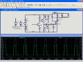
You'll be glad to know that I figured out at least some of what's going on.

Q1 was bouncing in and out of saturation, which was causing a good bit of ringing. The change should be pretty easy. The PWM from the PIC goes directly to the base of Q1; and the 1k resistor that was on the base of Q1 gets moved to between the emitter-ground junction. The 330 Ohm resistor R2 gets removed entirely.

Note that I've added some caps at the driver; a .1uF and a 22uF cap from the digital supply to digital ground.
Note that I also added a small cap across the motor (C3) and another (C4) across the lines to the motor (this would go at the power relays).

Lwire and Lground represent the inductance & resistance of the wiring between the 12v supply and the driver board. I'm assuming that the driver is currently supplied by the motor wiring.
Lwiremot1 and Lwiremot2 represent the inductance & resistance of the wiring between the motor and + supply, then the motor to the MOSFET.

Not knowing the inductance of the motor, I just threw in 2mH; it's undoubtedly a lot larger than that - but I wanted the simulation to finish today. ;)
 

Attachments

SgtWookie

Joined Jul 17, 2007
22,230
OK, found a somewhat more obscure problem - and it's directly related to grounding.

If the MOSFET driver is using the same power ground that the motor is, when the MOSFET turns off, the ground at the driver will drop over a volt - below ground!

Even though the PIC PWM output is at 0v, the base of Q1 gets current, because its' Vbe exceeds cutoff (about 0.5v). This causes Q2 to conduct, etc... partially charging the gate of M1 until it starts conducting, which pulls the ground at the driver back high - turning off Q1, which turns off Q2, turning on Q3, and pulling the gate back low.

Which causes the ground to drop below -1v again. This cycle repeats several times until it plays out; even with the changes I made in the last update. It's due to the resistance and inductance in the AWG14 wire over that 20" between the PIC board and the driver board.
 

Thread Starter

RobbJohnson

Joined Dec 15, 2009
76
I really don't want to shorten up everything to a point where I can't work on it or arange the items in the tank. I will try to increase the size of the wire to say 10 gauge from the battery to a point close to the mosfet (say an inch or two).

I'll do this, and make the circuit changes this week. I have a friend who makes battery packs, and i am going to have him make me a 5volt rechargable pack with charger, not sure what chemistry yet.

So, I've got a lot of rebuilding to do.
 

SgtWookie

Joined Jul 17, 2007
22,230
I have another alternative.

http://ca.mouser.com/ProductDetail/...GAEpiMZZMuIaPd8bG7xI2rs3jzWzD%2b8wQZ4uC1dNfo=

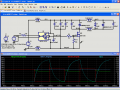
The Avago HCPL-3120 will replace the entire driver circuit, and should get rid of the sinking ground problem causing ringing on the gate.

They're only $2.37/each - I'd buy 10 of 'em to get the price break.

See the attached for how much more simple it'll be.

I didn't include the simulation, because it requires a SPICE .mod file and symbol to run it.
 

Attachments

Top