25 amp motor controller help

Thread Starter

RobbJohnson

Joined Dec 15, 2009
76
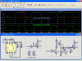
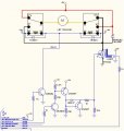
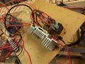
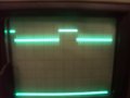
I changed from a 2 amp motor to a 22 amp motor. I trippled the Irdz44 as shown and increased the size of the protection diode. My problem is i am over heating the diode and blowing the fets. the input signal is a 15 khz pwm signal from a microcontroller. At very slow speeds it does work but starts to over heat. the motor is running at 12 volts.
Any help would be appreciated.

P.S. this is my first post, I hope the drawing comes out ok.
 

Attachments

SgtWookie

Joined Jul 17, 2007
22,230
Hi Robb,
Well, when the MOSFETs turn off, guess where the 22A they were conducting goes?

Through the diode!

And your diode is only rated for 6A.

You get by with it at low motor speeds, because the average current through the motor is much lower due to the PWM. However, as the PWM ratio increases, the current through the diode increases when the MOSFETs turn off.

I hope you aren't driving those gates directly from the microcontroller; they represent a large capacitive load, and really need a low-side MOSFET gate driver IC, or a home-made driver circuit.

Oh, the 1N4004 really isn't doing anything; the IRFZ44's have intrinsic body diodes.

You need something like this:
http://search.digikey.com/scripts/DkSearch/dksus.dll?Detail&name=MBR40250TGOS-ND
Rated for 40A, 250V. about $2.09+shipping.
 
Last edited:

Thread Starter

RobbJohnson

Joined Dec 15, 2009
76
Thanks, I'll order the diodes. And yes I have been driving direct. Would a you recommend something like a 2n2222 or 4n36 optoisolator, or something more exotic?
 

SgtWookie

Joined Jul 17, 2007
22,230
Ouch! Your poor, poor, I/O pin. :(

And your ever-so-toasty MOSFETs! (You're trying to use standard MOSFETs as logic level MOSFETs - that's a no-no)

Have a look at the attached. You might have to click on it after it comes up to see it full size.

Ignore the 555 timer portion on the left; it's just simulating operation at about a 45kHz rate. I deliberately ran it at a higher frequency just to accentuate the performance difference.

The MOSFETs I used in the example are IRF1405. These have a much larger total gate charge than a single IRFZ44, (about 170nC compared to 65nC)

M2 is an equivalent of how you're driving your MOSFETs, but in your case it's actually much worse - your I/O pin is limited to 20mA source/sink, but you're trying to get 1.5A peak out of it. (5v/(10 Ohms/3)) = 1.5A)

The top plot in red is your MOSFET (M2) gate voltage. Notice how low in amplitude it is, and how slowly the charge builds up and discharges. This is Not Good. The top plot in cyan is the M1 gate voltage. Notice how comparatively quickly it builds all the way to 12v, and also how comparatively quickly it discharges.

The 2nd plot is power dissipation in MOSFET M1. There are momentary peaks of high power dissipation as the gate voltage transitions, but these peaks are fairly short in duration.

The 3rd plot is power dissipation in YOUR MOSFETs. VERY high. You want the power to be dissipated in the motor, not the MOSFETs.

I didn't show the power dissipation in the load, but with the way you're currently driving your MOSFETs, you're wasting about 70W heating up the MOSFETs, and delivering a peak of 120W to the motor - but that's the absolute peak.

If you were using the driver circuit, you'd be delivering 270W to the motor.

Rload is a representation of your motor's load, by the way.
[eta]
If you want to substitute transistors:
Q1 - 2N3904
Q2 - 2N2907
Q3 - 2N2907
will work OK.
 

Attachments

Last edited:

Thread Starter

RobbJohnson

Joined Dec 15, 2009
76
Thanks so much. Looks like I have a lot to do, Wished I haddent ordered all those z44's. Best reguards,
Robb
P.S. if i use the IRF1405 do you think I can just use one per motor, and of cource using the driver circuit?
 
Last edited:

SgtWookie

Joined Jul 17, 2007
22,230
Nothing wrong with IRFZ44's. You know they're rated for 49A, right?

You could just be using a single IRFZ44 MOSFET; it's rated for twice the current you need. Your big problem was not getting the Vgs high enough, so you were dissipating LOTS of power in the MOSFETs themselves.

I guess I should've explained the driver circuit, so I'll do that now.

R1 limits the base current to Q1. It's not heavily saturated, so it'll turn off more quickly. There will only be a 4.3mA output current load on your PIC I/O pin.

Q1 sinks current from the base of Q2 via R2.
R3 provides for a reduced turn-off time for Q2 when Q1 turns off.
Q2 sources current via D1 and R5 to the gate to charge it at a peak 600mA current rate. R5 snubs any ringing tendencies due to the LC of the gate and the inductance of the wiring. In case R5 or other part of the driver fails, R11 turns off the MOSFET gate; it is for safety.

When Q2 turns off, the MOSFET gate is charged to 12v or so. R12 starts sinking current from the base of Q3, turning it on. D1 prevents the charge stored in the gate from trying to turn off Q3; instead Q3 saturates and provides a quick discharge path at nearly 500mA peak current for the gate down to around 0.7v; well below the threshold voltage.

After looking more closely at the simulation with the substitute transistors, R2 should be changed to 330 Ohms 1W, R3 changed to 2.2k Ohms, and R12 to 330 Ohms 1W. It would be a good idea to use a 1W resistor for R5 as well. It dissipates some power during gate charge/discharge. Note that reducing these resistors will increase peak power dissipation in Q2 and Q3; you should heat sink them. If you can't figure out a good way to heatsink them, then keep the values as shown.

The peak power dissipation in the MOSFET with the driver circuit only occurs for around 0.13uS when charging the gate, and about 0.2uS when discharging it out of a clock that's about 21uS. You're going to be running at 66.7uS per clock.

If you want to get really slick about things, you could use a P-ch power MOSFET as a synchronous rectifier instead of that big 40A diode I pointed you to. With just a plain rectifier, you'll have a voltage drop, which causes power dissipation as heat. If you use a power MOSFET as a synchronous rectifier, it acts as an "ideal diode"; almost no voltage drop across it. This will make your rig much more efficient.

However, it will complicate your programming, as you will need to add "dead time" between turning off the N-ch MOSFETS and turning the P-ch MOSFET on, and also dead time after turning the P-ch MOSFET off before turning the N-ch MOSFETs back on.

You'll also need a driver similar to what I've shown, except flipped upside down.
 
Last edited:

SgtWookie

Joined Jul 17, 2007
22,230
P.S. if i use the IRF1405 do you think I can just use one per motor, and of course using the driver circuit?
You could do that and it would work.
You could also use one of these instead:
http://search.digikey.com/scripts/DkSearch/dksus.dll?Detail&name=IRLB8748PBF-ND
Rated for 78A (limited by the package), 65A (limited by the silicon), but they have a gate charge of only 75nC; where the IRF1405 has a 140nC gate charge. That means the IRF1405 requires nearly twice the charge/discharge current of the IRLB8748 - and they're logic level, too.

For this purpose though, I'd suggest driving them using the circuit I posted, or buy a dedicated driver IC.
 

Thread Starter

RobbJohnson

Joined Dec 15, 2009
76
The circuit seems to be running ok, havent fully tested it yet. Attached is the scope at input to driver and output at the gate to the IRFZ44.
Thanks once more.
Robb
 

Attachments

SgtWookie

Joined Jul 17, 2007
22,230
What are you using for a power supply? It looks like you're getting peaks up to 18v on the gate, which is more than it should be.

I thought you were using a 12v lead-acid battery for a supply?

Looks like you're getting a bit of ringing during gate charge and discharge. Try putting a 0.1uF capacitor from the emitter of Q2 and high side of R3 to ground. A poly cap would be fine.
 

Thread Starter

RobbJohnson

Joined Dec 15, 2009
76
This new version has lots of digital noise (motor noise) on the power buses and the actual signals. I tested to make sure the diode is correct and good. Even used a small 12V computer fan as a load, which had the same problem. The large Motor turns on, runs for about a second or two slowing down and then speeds up again to repeat the cycle, ignoring the pwm signal. Pretty sure it running on its own induced current. The noise is so bad it took out the 16F1934 I am driving it with. I did not experence this noise with the old circuit, so i tried paralleling a 1n4002 with the large diode and the little motor, just for gigles, no difference.
 

Attachments

SgtWookie

Joined Jul 17, 2007
22,230
OK, what size wiring are you using?
22A is going to need some pretty heavy-gauge wire. If you have long runs, you'll have quite a bit of inductance, which will foul things up considerably.

It would help a lot if you could take photos of your setup and post them.
 

SgtWookie

Joined Jul 17, 2007
22,230
I see lots of long and loopy wires! :eek:

The scope intensity is a bit too high, and the pic is out of focus. Looks like there is some ringing at maybe ground level?

Where were you reading that from, and what's the V/div scale setting and probe attenuation?
 
Top