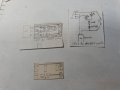
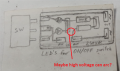
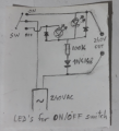
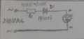
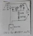
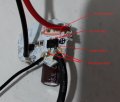
Oh, this might help you, this is before I soldered anything. Its a clean view of my cardboard electronic board and it shows where is the INput and OUTput for the 240V:
The load are the 2 color LED's which they open 1 at a time (not both at once). So 2V @ 20mA approximately.
An arc is usually visible as a blue or violet color between 2 metallic elements and from what I know, they start to appear over 1kv or more. I really dont think an arc might be the cause, especially for such low voltages, I would have seen it with my eyes. And that gap is about 5mm wide. Its an interesting observation though. Tell me how to test for arcs? Or at least how to protect it. I know 1 way is to enlarge the distance between the metalic elements in the circuit. Hmmm.... But until then, lets assume its not an ark. I am keeping in mind the arc posibility though. I am not disregarding it, but Im also trying other possibilities.
I believe we need some sort of filter in the input, where the 240VAC comes in the led driver board. A snubber perhaps? Or just a simple capacitor placed strategically? I was thinking maybe because I used 2 reverse paralel 1n4148, maybe they were overpassed by the current? Like they were not strong enough to face the spike? Should I change them for 1n4007, which are 1kV rated? While 1n4148 are for 70V constant and 100V for repetitive peaks (or spikes).
My goal with the osciloscope was a very good one. I was hunting for the spike. And if it was visible on my osciloscope, I would have experimented with everything, every compoents until I could find the solution. But without an image of what is happening, that can show me what is going on there, I am blind. I only can guess what may be. And you as well.
I was also thinking... maybe on paper everything looks nice and logical, but in reality, something else happens.
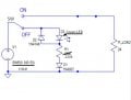
I suspect, that this circuit:
is having an issue with the switch. I suspect the switch might create in-rush currents for the leds. I think, maybe I should put a pair (100k and 1n4148) for each led and not only one pair for both leds. Maybe there are inbetween interferences from the switch that are overwhelming or overriding that single pair. I notice the first to burn up is the green led. It takes more number of switches for the red to burn up.
I failed to mention that the leds are absolutely fine and working while they are in working mode. They get damaged only in the switching moment.
Im also thinking to add a coil, to limit the inrush currents or spikes. Long as 1 meter, winded around a wood stick. I believe it will slow down and diminish any spike may be occurring. Its my theory. I didnt try anything yet, im just popping ideas on the table. Remember, its only happening in the vecinity of this SMPS (switch mode power supply) of the power LED's used for illumination. Not when the circuit is tested alone.
Your 240VAC has peak voltages of 340V but the 1N4148 diodes breakdown above only 100V.
1/4W European or American resistors are rated for only 200V. Chinese resistors might breakdown with only 100V.
So use higher voltage rated parts.
Trace the circuit when the switch is in the off position. there is a current path through the left LED, through the diode protecting the right LED, through whatever the 240 V load is, and back to the 240 V source.
Break the connection between the left and right LEDs, and add a second 1N4004 and resistor. This makes the two LED circuits independent of each other and removes the sneak path.
This would be a lot easier with a unique reference designator for each component.
- And with this project I am learning new things about diodes !!! I was always looking in the datasheet for (any) diode, if they are used for --rectifying-- but I neglected the --fast switching-- side. I believe, every diode is a rectifying diode (corect me if im wrong), but it is the only solid thing I know about them and thats what I was looking for all the time in the datasheet. Especially for 1n4148, in some datasheets they didnt mentioned it and I was asking myself why and looking specifically for this characteristic. And in other datasheet I found it mentioned and aaah, I was satisfied and thats it.
- I know you and others, mentioned to me many times to change from 1n4148 to 1n4007, and I didnt do it because multiple reasons in my head. 1-it is a small diode in physical size than 1n4007; 2-both are a rectifying diodes; 3-I have a lot of them in my drawer and I must use them,right? Haha. 4-NO 1n4148 was damaged or burned while exposed to the mains (most certainly) spikes, so in my mind it is "good enough".
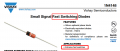
- But now I had a revelation, and a damn good one, thanks to your comment, I re-looked into 1n4148 datasheet and I realized it is a --fast switching-- diode. Hoopaaaa!!! What the hell? --I said, I dont need to be fast, to allow that spike to be read further in the circuit, I need it to be slow switching ! And I realized it when I see that "Extreme fast switching" in the datasheet. Wow. Right? Wow because im thinking from the circuit perspective, that I used a fast switching diode to defend against a spike that is probably slower than diode switching time. - In a word, I need lazy switching diodes !!!
Is there a way to make it look like a diode is more lazy to open? I dont know, like adding a coil or a capacitor behind it ? For me is fascinating.
Thanks for the comments so far !
--------
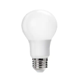
Aaaa.. I have an idea for someone who has a better osciloscope than I have here, who has a professional osciloscope that can measure into higher voltages like 300V or more, and not limited to 30V as my DSO138. You can take a led light bulb like this:
and solder 2 wires to its contacts, NO need to open up the interior of the bulb, and add my led circuit behind it, and measure if you can see or catch that spike. Essentially, what I have here is a led light bulb like this, that I dissembled and reassembled to fit my lamp. And you can use a normal led light bulb to replicate my problem that I have here, but on your bench.
You can use this: or this: --Make it simple enough, just to get the same issues as I have. And hopefully, measure them on your osc screen. If not possible, is fine, I thought to put the idea on the table because you can replicate everything I have here quite easy.
The series 1N4148 is NOT blocking the reverse voltage! It conducts after a reverse voltage iof 100V. The reason it is not destroyed is because the resistor is limiting the current to something it can handle.
And I have no clue what you are talking about in your last post. There is no inrush current in your circuit. Switches not create spikes, and a fast diode would block a spike faster (that is why it is called fast) than a slower diode.
You do not "need slow switching". For all of the diodes, including the two diodes that are protecting the LEDs from excessive reverse voltage, switching speed is irrelevant. Spikes are not what is killing your LEDs - 14 amps of line current is killing you LEDs because your circuit is incorrect.
What is important in your circuit is the PIV rating.
Peak Inverse Voltage is the maximum voltage the diode is rated to withstand (survive) continuous exposure to. For a 240 Vac circuit, the PIV is 340 V. Diode D1 in post #49 ***must*** be rated for at least 400 V.
A standard rule of thumb for long-term reliability is that a device should be rated for at least twice its application: Use a 25 V (or higher) capacitor in a 12 V circuit, and a 700 V (or higher) diode in a 340 V circuit. This is why we recommend a 1N4007. It is rated for 1000 V PIV, is almost as cheap as a 1N4148, and is known to be very reliable.
Change the diode. You should change all three, but if you don't change D1 it will fail.
Change the circuit. If you don't, it never will work.
ok, now I changed the diode into a 1N4007 (exactly as in mister @Danko circuit)
It burned another set of leds.
Then, Ive replaced the 100k with a 220k resistor. And put this time only a single green led, because they are the most sensitive. It worked for awhile, like 10-15 switches and it burned down. Daaaaaamn.
Im telling you and you should believe me. By itself, this circuit is working without any problems. But in the close vicinity of a power supply like I have here, it get influenced with some weird ass currents or voltages that I have no idea how to see them/measure them/catch them. I can only speculate. I believe is coming back from the power supply, from its large capacitor it has there 3.3uF@400VDC . Its the only explanation I can think of.
- What other protection should I add now?
If it helps, this is a little bit from the power supply of the power leds that are the continuation of this switching leds circuit: --
We must keep in mind this is also in the same circuit and it is influencing somehow my switch LEDs circuit.
Is there a possibility to see what is going on ? To see that high voltage or current whatever it is? It would be nice to see it. Mmmmm.
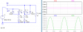
It is your circuit with my recommendation about 1N4007 diode.
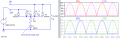
Also, diagrams showed you big current through D2 - D5 (14000mA peak instead 20mA max. allowed).
It is why your LEDs and diodes become damaged.
Below is working circuit, where LEDs current is 1.25mA RMS.
It is what @AnalogKid, talked to you about:
Break the connection between the left and right LEDs, and add a second 1N4004 and resistor.
This makes the two LED circuits independent of each other and removes the sneak path.
I've done a single led experiment already, right before your last comment, i said: "Ive replaced the 100k with a 220k resistor. And put this time only a single green led, because they are the most sensitive. It worked for awhile, like 10-15 switches and it burned down. Daaaaaamn. "
Here is how it looks, using your last schematic:
In other words, if I use double or single branch, it will still burn the led.
I assume is turning back from the power supply because by itself, this circuit works fine.
But you (dont say it out loud) I think you think it is this single circuit fault design alone.
And I am considering every angle, I only want this thing resolved. And I realized the ONLY common thing that we neglected all this time is the switch. Although in the past I did made the switch test a lot of times on the stand alone circuit and everything was fine. But maybe, in this particular case... who knows? maybe the damn switch is creating more oscillations than it should.
I remember in the past, in the 90's I saw capacitors soldered directly on the switch pins, and someone told me the reason was for the sparks inside the switch to be eliminated.
I definitely need more protection for this simple circuit. So I'm starting to assume something else. What if I receive 1kV on this circuit instead of 240V? or 360V as you calculated before. I have no means to measure it, or to actually see it, even with my mighty osciloscope DSO138; and my only chance here is to imagine a "what if" scenario. So What If is 1kV on this circuit lines? What protection must be made to make it work in safe conditions? Smart, right? I am impressing myself as well. Haha.
With a 220K series resistor it does not seem like it would be a forward current problem, but still that 1N4148 is not suitable for a mains circuit because of it's low voltage and current ratings. So how about a CLAMP diode arrangement to limit the forward voltage across the LED. Consider that the input to a switcher supply is a rectifier feeding a capacitor, worst case you might get that capacitor voltage PLUS the mains peak voltage as the switch is opening. And as the failure seems to happen when the switch is operating, that is one more possibility. So a string of forward biased diodes across the LED so that they will conduct before the voltage becomes excessive.
A simpler thing will be to put a capacitor across the LED, 0.1 mfd, or even 0.47 mfd, as an experiment. Whatever spike is happening is probably quite narrow, and so a cap might be the answer.
In a recent post the TS does mention that it is directly related to the switcher power supply.
I do see some big sparks when I plug in a portable computer's supply, not every time, but occasionally. The supplies involved are not aftermarket junk, but mostly OEM units that work well for every day operation.
The simple work around would be to use a neon indicator instead.
MisterBill2, the 1N4148 diode is parallel with the LED then its reverse voltage is simply and only the low LED voltage.
It is the low voltage rating of the resistor (200V) that breaks down with the 340V peak of the electricity, or even higher peak voltage caused by the inductance of the power supply and "switch bounce".
When the resistor breaks down then it is a piece of wire causing a massive voltage and current through the LED.
Hi Bill,
It is not the power rating of the resistor that is the problem, it is possible that the voltage breakdown of the resistor has been exceeded.
E

 Facebook
 Google
 GitHub
 Linkedin