240V indicator led at input of a power supply.

Status
Not open for further replies.

dl324

Joined Mar 30, 2015
18,449
I am asking you now, what else is there for measuring with more precision and more rezolution?
What you did is basically what a scope probe would do. But the probe would use precision resistors because errors in the voltage divider would affect your measurements. They'd also typically have some capacitance in parallel.
 

Thread Starter

q12x

Joined Sep 25, 2015
2,227
Hantek PP-80 X1-X10 Probe
(Did you watch my awesomeness video? I think you put that protection 1n4148 in reverse paralel to the LED as a response to my circuit I build and used already.)
Thank you mister @Danko ! I have an exact model of the probe, I buy it after I got DSO138, and I have use it ever since. I never switched it's option X1-X10 that often to be honest. I only set it to X1 from the start, and forget about it. I guess I should play more with this option to get use to it's existence. But it was not enough either way, because my X100 or 1/100 as I call it, is what is required for my mains measurement. So its better to have 1/100 and even 1/1000.
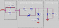
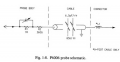
Thank you for the circuit of the probe ! that is very interesting to see ! One thought, your circuit that you choose, it is not as simple as I expected! I never searched for such circuit, is a good idea you put it on the table. Saying that, I just give a thorough search on google and I find your picture and it's related page, and also many other sample circuits, more simple and more direct. I think this is closer to what I made already, more simple to understand and efficient:
1647787237025.png
Its interesting for me to see this construction. So the voltage divider is 9M in the tip of the probe and 1M inside the osciloscope and the output is taken across 1M further inside oscilloscope. And between the resistors, there is some fine adjustment circuitry. I really like simple and to the point circuits! So you remember this about me, I am not an electronist or electrician, I am an artist who happen to know a lot from many-many fields.
Yes, very interesting. What I am more interested than the probe circuit, is to have the capability of zooming inside the X100 waveform that I took with my pink circuit, and see more detailed fluctuations that are happening there. But this is done only in software and my DSO138 has no such advanced option. I mean, it can zoom in, to 10us I think it was, but the speed is so fast, nothing is rendered on the screen. And it has a hold button but you must try it 100 times until you can catch something by pure luck and even then you wonder if its buggy or the real thing, because this osciloscope is very rough and trembling all the time. Even with this special probe PP-80. It's just how it's made. In a word, I need a much more better osciloscope for what I want to see and research. Eh well, we live with what we have, right? This is it about this subject, we stretch too long with it and I thank you so far !
 
Last edited:

dl324

Joined Mar 30, 2015
18,449
One thought, your circuit that you choose, it is not as simple as I expected! I never searched for such circuit, is a good idea you put it on the table.
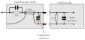
The voltage divider with capacitors is called a compensated voltage divider. The compensation is to prevent edge rounding on fast signals like square waves. On the rising edge, the initial voltage division is performed by the capacitors.

Probe construction isn't necessarily that simple. I recall reading somewhere that Tektronix invented some kinked wire for their probes; can't remember the details now.
 

Thread Starter

q12x

Joined Sep 25, 2015
2,227
Just for bragging purposes and if you enjoy some technical relaxation, I will post this video link :
But keep in mind this movie was made in the very beginning BEFORE creating this forum thread here. I was not planning to open any discussion about it here on the forum, if that problem didnt occurred. Interesting for you to see is my final experiment at the very end of the video, when I test it for 240Vac, nothing got burned. You must believe me, afte 1 or 2 switches (from the switcher I used) the green led burned out, like that. But not in my tests ! I still find this phenomenon weird, even after your explanations. But I learn what to avoid, right? Thanks for watching (if you'll watch it). Haha.
 
Status
Not open for further replies.
Top