240V indicator led at input of a power supply.

Status
Not open for further replies.

Audioguru again

Joined Oct 21, 2019
6,826
A modern resistor has a carbon or metal film that has a spiral cut in it. The gap of the cut is very thin with a low voltage rating (arcing). The distance from one gap to the next gap is very small. It is protected with a paint coating.
If the resistor is a cheap one made "over there" then its quality is poor and it breaks down at a low voltage.

The 240V squared/220k= 0.26W but for half the time so it dissipates only 0.13W which is within the power rating for a 0.25W resistor.
Do cheap resistors have any voltage rating??
 

Danko

Joined Nov 22, 2017
2,224
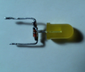
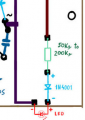
Move diode 1N4148 from cardboard to LED.
Solder it as close to LEDs cup as possible, with shorttest diode leads.
Will see test result.
1647282096382.png1647281996863.png
 
Last edited:

Thread Starter

q12x

Joined Sep 25, 2015
2,227
So how about a CLAMP diode arrangement to limit the forward voltage across the LED. Consider that the input to a switcher supply is a rectifier feeding a capacitor, worst case you might get that capacitor voltage PLUS the mains peak voltage as the switch is opening. And as the failure seems to happen when the switch is operating, that is one more possibility. So a string of forward biased diodes across the LED so that they will conduct before the voltage becomes excessive.
A simpler thing will be to put a capacitor across the LED, 0.1 mfd, or even 0.47 mfd, as an experiment. Whatever spike is happening is probably quite narrow, and so a cap might be the answer.
Can you make me a circuit from all your explanations? I read about what Clamp means and what is used for. It is only shifting the entire oscilation more into positive or negative in respect to 0V. I think you are referring maybe to something else than this shifting I read ? Thats why I want a circuit from you.

This is the best image that represents what Clamp Diode is made and is doing:
Read the voltages and you will see the shifting in voltage (-0.7V taken by the diode), instead of 10V on the output is 9.3V
1647343853142.png
I dont understand what is this good for and how to exactly use it/ apply it. Its a new thing for me, I admit.
But I love to learn new useful things! Who wouldn't?
I found a very good tutorial and straight to the chase: here

Did you try taking the power supply out if the circuit? Does it work without it?
-That's what I mean when I mentioned many times: "working by itself" and NOT in the same circuit with this power supply.

The supplies involved are not aftermarket junk, but mostly OEM units that work well for every day operation.
-What OEM stands for?

It is the low voltage rating of the resistor (200V) that breaks down with the 340V peak of the electricity, or even higher peak voltage caused by the inductance of the power supply and "switch bounce".
When the resistor breaks down then it is a piece of wire causing a massive voltage and current through the LED.
I think you have a spark of geniality. It is a very intriguing idea, that I never had thought of myself.
But keep in mind, that this resistors does work for 240V and probably higher when not in vecinity of a SMPS(switch mode power suply) or mechanical SWitches, like I have here. I believe these are the 2 big killers for my LEDs (especially for my VERY sensitive GREEN LED. He is the first to burn down and very fast, from 1 to 5 switches.) I suspect very high spikes from both of them combined. And those spikes have a great potential to spark across the tiny spiral gaps of the resistor as you mentioned. And render the resistor as a simple wire. We need to calm the f* down these spikes and make a smooth and awesome current entering this LED circuit. Pretty much like it is "working by itself".

An alternative would be to power the LED from the output of the supply.
Yes, haha, I know that, but this is more an experiment and a problem to be resolved and a learning lesson, for me at least. Hopefully for others as well. Its fun fingering 240V, you know? Hahahahaha.
This problem has more ramifications. For example: I have an old project where I put a similar in series circuit and from maximum 5 switches, and even without any switching, but only from working uninterrupted, the led you see there was burning up. Very unpredictably. It worked for awile and then I find it dead for absolutly no reason. I didnt switch anything. I changed that led 10 times, diferent models and colors, all they died, sooner or later. I suspect like 30kV in that ionizer, those high voltages can potentially spark even between the 2 legs of the diode itself and also of the led itself. I Never thought of mister @Audioguru again, spark across the tiny gaps of the resistor though. I thought of isolation in a blob of plastic or cement or whatever isolation, but completely melted around it to protect it from external floating ionizing 30KV influences that are clear there. But I've also though on a better & safer circuit for driving this LED. This is just a ramification, an example of completly other situation than near mechanical SWitches and SMPS like I have now.
Click this link and then click on the image to zoom in:
https://www.deviantart.com/q12a/art/20200823-Ioniser-852933049
1647345678973.png

Move diode 1N4148 from cardboard to LED.
Solder it as close to LEDs cup as possible, with shortest diode leads.
I didnt do anything YET, but I will do it as you say as well. Im waiting for @MisterBill2 Clamping circuit, and also I will try adding more higher resistance than 220k. I will go to 1M and get down from it until the led is lit. I EXPECT some led flickering when I am switching, I really want to try to catch that spike somehow. A hint from when is occurring. So in the same time I am thinking of a spike visualizer. Cool, yes? Haha.
Sorry for this long ass reply ! I know, it is longer than usual.
 

Danko

Joined Nov 22, 2017
2,224
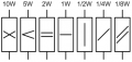
Max. working voltage of resistors:
1647353187069.png
For example:
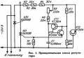
In year 1985 I published circuit, where for good reliability
I used 3 connected in series 0.25W resistors (R2, R3, R4) as ballast:
1647356488974.png Circuit.jpg
 
Last edited:

Thread Starter

q12x

Joined Sep 25, 2015
2,227
To mister @Danko , that is an excellent information about max. working voltage of resistors, thank you !
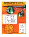
Is that a Miniature Regulator for soldering iron? It is very nice !
What is the \\ marking meaning? Screenshot_3.jpg I can see with only one \ marking as well Screenshot_2.jpg
And I guess those are GPT? (General Purpose Transistors)? Correct? their equivalent may be BC548 ? or more powerful like BD139?
Its a very nice project, I personally love it !
 

MisterBill2

Joined Jan 23, 2018
28,055
OK, a fair question, what does OEM mean?
OEM = Original Equipment Manufacturer, the company that built the whatever. Everything else is "aftermarket."
 

Danko

Joined Nov 22, 2017
2,224
Last edited:

eetech00

Joined Jun 8, 2013
4,724
We must keep in mind this is also in the same circuit and it is influencing somehow my switch LEDs circuit.
Is there a possibility to see what is going on ? To see that high voltage or current whatever it is? It would be nice to see it. Mmmmm.
I think there is an smps startup input surge current that is damaging the LED's.
Try inserting a 10-25 ohm power resistor in series between the smps +bridge output and smoothing capacitor.
The resistor power rating depends on the value of the converters input smoothing capacitor.
If the cap has a low value (like 3.3uf) then a 1W resistor should be ok, but if higher could be 10W.

Tread carefully and observe/respect all high voltages...
 

Thread Starter

q12x

Joined Sep 25, 2015
2,227
I had the bright idea to google for "eliminate sparks over switch". And I find this very nice tutorial where they mention this:
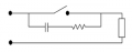
"The capacitor charges at a rate faster than the contacts open which prevents an arc from forming across the contacts. " for this type of circuit:
1647446946248.png
And I said, "AHA", and I filtered everything in my circuit using only capacitors of 10nF@2Amps (2A103J is their marking).
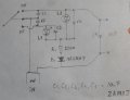
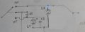
Unfortunately nothing worked. I started with a few capacitors, and then i've added more and more until I reached at this circuit here:
20220316_181649.jpg
- Ive noticed an improvement only when I had L1, it's C3 and C2 mounted. I didn't had the other capacitors installed and also no L2. It worked absolutly fine. I switched, like 50 times and nothing, the led didnt burned at all. But in the momment I've added L2 into circuit, L1 burned after 3 or 5 switches and soon after, L2 as well. Then, I said, well, L2 didnt had it's filtering on it so Ive added all of those capacitors you see in the circuit, to cover everything possible. What happened, was a burst of flickering until both leds died off. Today, in this experiment I burned 10 leds. I dont like it, but I have to find a solution and the real cause.
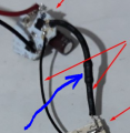
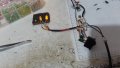
- I made an interesting experiment: When I had only L1, it's C3 and C2 mounted, basically 1 branch, but L2 positive wire disconnected - see the image I post with 2 blue dots - , well, as I mentioned already, in this configuration, no matter how many times I switched, nothing burned off, great right? Well, in the moment I touched the positive side of the led to the ON wire, the 2 blue dots in the picture, a good amount of spark come out and L1 burned off almost instantly. both leds burned off but when I was sparking (touching the 2 wires/2 blue dots) more times on-off, the leds were glowing with their last breath of light, very dimly and on the 30'est spark, both died completely.
Screenshot_2 copy 1.jpg
The conclusion of this experiment is that this Second line has an enormous impact on this leds circuit ! We must find a solution to separate the 2 branches of leds somehow, not to influence one on the other. My idea I said it before, is to make 2 separate led+res+diode in series, per each branch and not have a single res+diode for both leds like it is now. This experiment I will make next.
- Mister @Danko suggestion is a good one, to move the diodes on the leds itself. It didn't blow up anything, but both leds are staying lit, and the light is not turning off. It's clear there is a leak somewhere, and yes, I did mount everything correctly because I have the experience to be stupid and make shorts on 240V, so I am extra careful when dealing with circuits at this voltage level.
And as a hint, I'm always keep the negative leads shorter and the positive leads longer, intentionally, because it helped me identify very quickly in my past experience. So you can see in the picture, the leds longer leads and straight are the positive and the bent and shorter leads are the negative. Also the wire color I used are the proper ones, black for neg and red for pos. Its very good to have everything very clear when doing experiments. It's faster and safer.
See the video (20seconds long) : 1647451109130.png
Don't forget to check these 3 last pictures as well:
20220316_183716.jpg 20220316_184138.jpg 20220316_184434.jpg
 
Last edited:

Thread Starter

q12x

Joined Sep 25, 2015
2,227
Alright!!! I made it work !!! As I originally intended !!! So the answer is to use 2 separate branches of resistor+diode and also 4 wires for the leds and not 3 with a common negative. If you want to burn a lot of leds and not work at all, do it as I did it until now.
But wait! it didnt work from 1 shot either. 1 led was always open. It turn out I left 2 capacitors on the switch and the one for the ON position, was conducting enough to light the led all the time.
1647615063977.pngRemoving both (anti-spark) capacitors from the switch, solved the problem completly.
Now When I turn ON the lamp from the switch, the green led is lit, and when I turn OFF the lamp, the red led is lit and the green is off completly (when I had the capacitor, it was still staying lit). I also made the switch test, interrupting like 50 times and everything stay alive and in nominal parameters.
This is VERY COOL ! Problem Solved !
 
Last edited:

Thread Starter

q12x

Joined Sep 25, 2015
2,227
- So to be more clear, because I am not stupid, I did used quite a lot the 1 branch circuit before in one of my projects. But now looking back and re-thinking everything, I do see the differences. But I don't understand why exactly is the cause for it not working at 240V. If you can to give your opinion, anybody really, is welcome with any possible argument.
- So the original circuit I used (with 1 branch), was already implemented for my (2in1) 2 electronic gadgets that are powered from a single 9V transformer:
1647633637737.png 20220318_220127.jpg 20220318_220157.jpg 1647634144108.png
- I used a 10k resistor for the 9V circuit, and you can see 103 marked on the resistor. So for this LOW voltage application, this arrangement worked without any problems, no leds are burning, everything is more than ok.
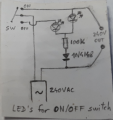
- By the way, I designed and implemented this 2 led switch circuit from the original with 1 branch that you see here with 9v and the other one that is for 240VAC. I didnt copy it from anywhere because I thought it must be too much to search for it, so I sit down and draw it until it worked. And it worked from 1 shot when I was dealing with low voltage.
- Now with the 240AC .... wow, what a ride. I was so sure it will work. Something is keep burning the leds in this configuration. I plan to make a quick movie about it because is an interesting experience and I have many details to explain. So this is the difference I wanted to show you here. Until I will finish the movie, maybe you give me your idea what might be the cause for high voltage versus low voltage on 1 branch.
Thank you being with me so far.
 

dl324

Joined Mar 30, 2015
18,449
Is the switch in this circuit a toggle switch?
1647635320295.png
This circuit should be problematic because the signal diode and LED will both be breaking down. To protect the LEDs from reverse breakdown, the diode needs to have a breakdown voltage higher than the peak AC voltage applied.

If you're using 1/4W resistors, you're operating them beyond their maximum working voltage.

Glad to see you were able to get a DSO138.
 

Thread Starter

q12x

Joined Sep 25, 2015
2,227
Is the switch in this circuit a toggle switch?
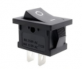
Is this model of toggle plastic switch: (you can see it in my earlier photos as well from a side)
1647638183529.png
Funny story, it had exactly 2 pins as in this photo (form www), but the case was having 3 holes for the 3'rd pin only they didnt put it. So I cut and bent a piece of solderable metal sheet, and made my blody pin which is working perfectly right now. HAHA, in your face, Chinese industry trying to screw me with a missing pin! Hahaha
So now is having 3 pins exactly as in my circuit, the middle is common and the other 2 are the actual contacts.

This circuit should be problematic because the signal diode and LED will both be breaking down. To protect the LEDs from reverse breakdown, the diode needs to have a breakdown voltage higher than the peak AC voltage applied. If you're using 1/4W resistors, you're operating them beyond their maximum working voltage.
So, you say the cause is ... reverse breakdown or Over Voltage for led, diode (and resistor). I see.
Thank you for your input.

Glad to see you were able to get a DSO138.
Oh that is old and rusty, I want a (professional) new one ! Haha. But thanks for the advice here on this forum I bought it, more than an year ago, I think. Thank you for noticing. I want a professional oscilloscope that can measure up to 1kV signals on its probes, because I really have to see some things that otherwise I can't. I'm still a rookie in using oscilloscopes, I admit. Still, much to learn.
 

dl324

Joined Mar 30, 2015
18,449
So, you say the cause is ... reverse breakdown or Over Voltage for led, diode (and resistor).
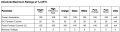
A 1N914/1N4148 signal diode will have a maximum reverse voltage of about 75V.
1647641175803.png
Note that devices aren't guaranteed to survive absolute maximum ratings.

These LEDs have an absolute maximum reverse voltage of 5V:
Kingbright
1647641306762.png
1647641285500.png
I want a professional oscilloscope that can measure up to 1kV signals on its probes, because I really have to see some things that otherwise I can't.
All you need is an appropriate probe. I think I have one that will handle thousands of volts (at least 1000).

Don't forget that the maximum voltage you can have on your scope input is around 50V. With a 10:1 probe, that means 500V. With a 100:1 probe, you could measure up to 5000V (just make sure the probe is rated for a voltage that high).

The 240VAC you're working with is RMS. For the components and scope, you need to consider peak or peak-to-peak voltages.
 

Thread Starter

q12x

Joined Sep 25, 2015
2,227
I made a movie where I show many things and it is a bit long (34min)
Now it is assembled and working as I originally intended. What a project. :)
 

MisterBill2

Joined Jan 23, 2018
28,055
Regarding a higher performance scope, and higher voltages: There are many different scope probes available, including ones suitable for probing higher voltages.
The maximum voltage rating for scope probes is IMPORTANT!! Aside from the instant destruction of either probe, scope, or both, there can also be a shock hazard. Not al brands of scopes have adequate protection of the inputs, and so they are not going to be usable after one $2500 over-voltage incident. That is why I am posting this precaution.
I was not involved with the "incident", except for evaluating the scope afterward to see if repairs could be done.
 

Thread Starter

q12x

Joined Sep 25, 2015
2,227
To @MisterBill2 Apropos high voltage probes for my osciloscope:
I mentioned already and I will mention again. I made myself this 1/100 fixed rezolution pink probe extender for my dinky osciloscope DSO138 that has a maximum of 30V to be measured on its probes. I learned this important property and I am keeping it in mind all the time when probing anything. I would really hate myself frying my tool, as dinky as it is.
I probe with it the mains 240V and I could see the oscilation of the mains on 5ms dial of the scope as 2.4V sinusoid.
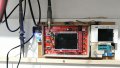
20220319_152353.jpg 20220319_152442.jpg
But I couldnt see any spikes or any small fluctuation, because it has no idea of zoom in. On a professional scope you can hold still, record and screenshot a waveform and zoom in like 1000 times, with incredible resolution and see some unpercivable fluctuations or spikes or anomalies. What I have here...is a toy and im aware of it. But I managed to create this little probe extension that is allowing me to measure well beyond it's input of 30V limit. I didnt copy this from anywhere, I thought of it long time actually and 1 day I decided to try and in some degree to risk it. And it worked perfectly with no incidents, and im very proud of it. I am asking you now, what else is there for measuring with more precision and more rezolution? A better probe extension circuit will be cool.
- I know some "advanced" things about osciloscopes in general because I watched a lot of videos on youtube and I get a good general idea about their performance, specificity, even software or some hardware advancements that they are better on newer models. Ofcourse, just watching is not equivalate putting your hands on it and playing with it until you get all the details and what it can really do. Im only an outsider observer because in this capitalism I am a poor soul and I dont dream things will get any better. Im as realist as I can be.
 
Last edited:
Status
Not open for further replies.
Top