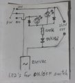
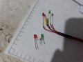
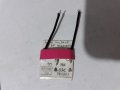
240V indicator led at input of a power supply.

Status
Not open for further replies.

Thread Starter

q12x

Joined Sep 25, 2015
2,227
I give up, what did you do?
Hello mister Steven ! Nice to see you.
And thank you all for your guesses.
Well, it is very simple. We must keep in mind these are not the "old GaAs" type of leds that we are used from the books and the 80's and 90's commercial market, but they are the new GaN technology. This thing I remember all the time, no problem. What I forget is that they are running at extremly low currents at a very hight brightness. So putting 10k was too high current - for THEM, not for the theory. And It did indeed blow up not one 10k but 3x30k in paralel and also 3x3k in series. The series didnt blow up as FAST as the paralel ones, but they were getting extra hot. I tested every thing was said here. (almost and in reason).
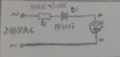
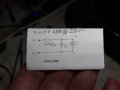
So, the actual circuit is like this:
20220220_010423.jpg
Where the resistor must have a very high value, D1 can be any rectifier diode with reverse voltage bigger than 300V I guess, and the led must be the newer GaN types (not the older GaAs), which work at incredible low currents I was very lucky to grab them, guess from where... mister ebay. Yes, they have wonderful things there, like gold in the mud, if you look closely. I was lucky I guess. I did get SMD 1206, 0806,0603,0402 LEDs in the same GaN technology. I guess its in the same ballpark by my EYE-ometer, since they all are pretty much the same brightness that is blinding if you stare 2 seconds in them with your naked and virgin eye.
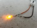
Here you can actually read that resistor value of 100k.
20220220_000405.jpg
Though in my final circuit I used a much higher resistor, in an attempt to lower the temperature down.
Remember (probably) that I have an interesting tool in my arsenal, " The Digital Thermometer". And I probe the resistor and the pin of the led. I was amazed that the very base of the led on the leg going down toward resistor, was hotter than the resistor. Very interesting detail that I was not really aware. Also if you drag the pin too much, force him, it will rip off from its plastic case, that is very fragile contact in there. I managed to rip one off and if I touch its pin, bring it back to its position, is working as a normal led again, but if Ilet its pin untouched, he dies back. Aaah. I have 100 of them so I dont have problem.
Today I managed to burn 4 leds, aaah. And 1 I broke its pin. So 5 damaged.
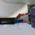
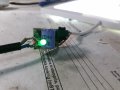
Here is the actual and final circuit on the same input 240V wires as planned in the start:
20220220_011607.jpg20220220_011607 Copy.jpg
Sorry for the long time delay until I responded (thats why I inaugurated the guess game, haha), but I had to also take some temperature measurements on the resistor itself, exactly in this circuit you see in the picture. Man, how much I stressed those 2 contacts on that green board...ohoa. But I am happy with the results.
Resistor Value Temperature in dgr Celsius (not Fahrenhight)
100k ~90*C
120k ~70*C
220k ~60*C
And the final resistor I used was the 220K.
Pretty much that's it.
I was curious what's the calculation saying for my last values I used here.
V=240V, R=220000R (220k), results I=0.00109 and P=0.261
Hmmm, not quite 1/4 (or 0.250W) for the resistor, but at around 60*C on the resistor, I think is a acceptable heat. I have the same circuit using 100k (at 90*C) running for years. Heh. I'm glad I can measure the temperature now,although a bit inconfortable to use its probe... I dream for a Flir thermocamera...ehee. but not in my life and I know it. Ehhh.
(Editation): Actually its 120V since its half of alternative wave that led is powered. So,
V=120V, R=220000R (220k), results I=0.000545 and P=0.0654
Thats it, thank you all for your help !
 
Last edited:

Audioguru again

Joined Oct 21, 2019
6,826
The little diode has the LED voltage (2V or 3V) alternating with 0.7V across it. The LED blinks at 50Hz.
The minus pin on the LED has the chip sitting on it so it is pretty large inside and it is the pin that gets the hottest.
 

AnalogKid

Joined Aug 1, 2013
12,241
Resistor Value Temperature in dgr Celsius (not Fahrenhight)
100k ~90*C
120k ~70*C
220k ~60*C

I was curious what's the calculation saying for my last values I used here.
V=240V, R=220000R (220k), results I=0.00109 and P=0.261
Hmmm, not quite 1/4 (or 0.250W) for the resistor, but at around 60*C on the resistor, I think is a acceptable heat.
No one else does. For decent long-term reliability, do not run a resistor at more than 50% of its rated power level.

(Editation): Actually its 120V since its half of alternative wave that led is powered.
No.

The reverse-polarity protection diode is conducting during the reverse polarity. Therefore, the current through the resistor is almost exactly the same for both AC power half-cycles. As above, to reduce the power dissipation in a single-resistor circuit, add a second rectifier in series with the circuit to block current in the reverse direction. This will bring the power dissipation down to a barely acceptable level.

ak
 
Last edited:

dl324

Joined Mar 30, 2015
18,449
So, the actual circuit is like this:
If you have a 1N4007, you can use the original circuit and reduce power dissipation in the resistor by 50%. I only suggested putting the signal diode anti-parallel to the LED because you weren't using a diode with a high enough reverse breakdown voltage.
 

Audioguru again

Joined Oct 21, 2019
6,826
Why didn't you do the simple calculation (219V squared)/10k= 4.8W then use a little 1/4W resistor to burn?
But at first your electricity was 240V so the resistor heated with (239V squared)/10k= 5.7W!
 

panic mode

Joined Oct 10, 2011
5,179
about circuit topology....

using diode antiparallel with LED protects LED from reverse voltage during negative half-period. in this case any diode can be used, breakdown voltage is not important, even another LED will do. but problem here is that it also unnecessarily allows current to flow through the series resistor even when LEDs is not lit. this means twice the power dissipation of the resistor and absolutely no benefit (such as light output) - just more energy wasted - more specifically that is doubling heat dissipated by the resistor.

therefore in application like this, it is better to use series diode (or add it as additional one) or ... use bridge rectifier and increase value of the resistor. since in this case diodes are in series with LED, they need to be rated for at least 400V.

about LED...

since the LED is current controlled device, and series resistor must be used and voltage drop across resistor is huge, it is better to choose high efficiency LED, something that works with 1-2mA, not 10-20mA. then series resistor can be larger value and lower power. with high efficiency LED needing only 1mA and series diode like 1N4007 your resistor need to be higher resistance (such as 120k) and that means less current and lower power resistor.

even better, do not use LED, go with a steampunk neon indicator and even higher series resistor. then current draw will be much lower.
 

Audioguru again

Joined Oct 21, 2019
6,826
I was going to say that the neon bulb on my 30 years old freezer is dead when I guessed that it lasted for 15 years which is 131,400 hours. Most LEDs are rated to last for "only" 50,000 hours.
 

panic mode

Joined Oct 10, 2011
5,179
example:
240V/1mA = 240kOhm if using bridge rectifier (full wave current through LED).

P= V*I = 240V*1mA = 0.24W so even 1/4W resistor would be ok.

Note that when using half wave rectification, current is only half so resistor value would need to be halved to 120k. Computer current would be 2mA (if full wave) but we are only using half of it so
P = V*I = 240V * (0.5*2mA) = 0.24W.

i would still pink 300 or 500mW resistor to have a larger safety margin or better use two 1/4W resistors.
 

Dodgydave

Joined Jun 22, 2012
11,395
Hello mister Steven ! Nice to see you.
And thank you all for your guesses.
Well, it is very simple. We must keep in mind these are not the "old GaAs" type of leds that we are used from the books and the 80's and 90's commercial market, but they are the new GaN technology. This thing I remember all the time, no problem. What I forget is that they are running at extremly low currents at a very hight brightness. So putting 10k was too high current - for THEM, not for the theory. And It did indeed blow up not one 10k but 3x30k in paralel and also 3x3k in series. The series didnt blow up as FAST as the paralel ones, but they were getting extra hot. I tested every thing was said here. (almost and in reason).
So, the actual circuit is like this:
View attachment 261091
Where the resistor must have a very high value, D1 can be any rectifier diode with reverse voltage bigger than 300V I guess, and the led must be the newer GaN types (not the older GaAs), which work at incredible low currents I was very lucky to grab them, guess from where... mister ebay. Yes, they have wonderful things there, like gold in the mud, if you look closely. I was lucky I guess. I did get SMD 1206, 0806,0603,0402 LEDs in the same GaN technology. I guess its in the same ballpark by my EYE-ometer, since they all are pretty much the same brightness that is blinding if you stare 2 seconds in them with your naked and virgin eye.
Here you can actually read that resistor value of 100k.
View attachment 261090
Though in my final circuit I used a much higher resistor, in an attempt to lower the temperature down.
Remember (probably) that I have an interesting tool in my arsenal, " The Digital Thermometer". And I probe the resistor and the pin of the led. I was amazed that the very base of the led on the leg going down toward resistor, was hotter than the resistor. Very interesting detail that I was not really aware. Also if you drag the pin too much, force him, it will rip off from its plastic case, that is very fragile contact in there. I managed to rip one off and if I touch its pin, bring it back to its position, is working as a normal led again, but if Ilet its pin untouched, he dies back. Aaah. I have 100 of them so I dont have problem.
Today I managed to burn 4 leds, aaah. And 1 I broke its pin. So 5 damaged.
Here is the actual and final circuit on the same input 240V wires as planned in the start:

View attachment 261093View attachment 261094
Sorry for the long time delay until I responded (thats why I inaugurated the guess game, haha), but I had to also take some temperature measurements on the resistor itself, exactly in this circuit you see in the picture. Man, how much I stressed those 2 contacts on that green board...ohoa. But I am happy with the results.
Resistor Value Temperature in dgr Celsius (not Fahrenhight)
100k ~90*C
120k ~70*C
220k ~60*C
And the final resistor I used was the 220K.
Pretty much that's it.
I was curious what's the calculation saying for my last values I used here.
V=240V, R=220000R (220k), results I=0.00109 and P=0.261
Hmmm, not quite 1/4 (or 0.250W) for the resistor, but at around 60*C on the resistor, I think is a acceptable heat. I have the same circuit using 100k (at 90*C) running for years. Heh. I'm glad I can measure the temperature now,although a bit inconfortable to use its probe... I dream for a Flir thermocamera...ehee. but not in my life and I know it. Ehhh.
(Editation): Actually its 120V since its half of alternative wave that led is powered. So,
V=120V, R=220000R (220k), results I=0.000545 and P=0.0654
Thats it, thank you all for your help !
If you use the circuit that i posted in #15 with the capacitor you won't get any heat and you can use a 1k5 resistor..
 

MisterBill2

Joined Jan 23, 2018
28,051
If it is a normal LED and there is nothing to limit the reverse voltage then destruction is assured. And I would not use a signal diode in a power circuit, ever. Now I see that it IS NOT our old friend "normal LED device", but something different the answer is clearer. And 68K was way too low from the start. I do have such an extension cord but probing the indicator will damage it.

And if this were a yootoob video I would immediately suspect that the actual supply was a 9 volt battery and every bit of it was faked.
 

Thread Starter

q12x

Joined Sep 25, 2015
2,227
AnalogKid: For decent long-term reliability, do not run a resistor at more than 50% of its rated power level.
I know what you are saying and I am keeping distange as a general rule from hot components as much as I can. But if this thing is only running hot, and not in other way,
I leave it as that. Remember, I tried to lower its temperature/power disipation, from 100k as usually was using for the old circuits,
now I jumped to 220K exactly in this mindset, to lower current and lower power disipation both on the resistor and on the led. But....it only likes one way, a bit hot.
dl324: If you have a 1N4007, you can use the original circuit and reduce power dissipation in the resistor by 50%.
Very Intriguing...I will test that. I will measure temperature for both variants: using 1n4148 and then 1n4007 !

dl324: I only suggested putting the signal diode anti-parallel to the LED because you weren't using a diode with a high enough reverse breakdown voltage.
and
panic mode: using diode antiparallel with LED protects LED from reverse voltage during negative half-period.
in this case any diode can be used, breakdown voltage is not important, even another LED will do. but problem here is that it also unnecessarily
allows current to flow through the series resistor even when LEDs is not lit. this means twice the power dissipation of the resistor
and absolutely no benefit (such as light output) - just more energy wasted - more specifically that is doubling heat dissipated by the resistor.
Absolutely amazing explanation mister [panic mode], simply fantastic interpretation and I personally love it.

panic mode: Therefore in application like this, it is better to use series diode (or add it as additional one) or ... use bridge rectifier and increase value of the resistor. since in this case diodes are in series with LED, they need to be rated for at least 400V.
I understand. I will do some tests and a movie about it.
Because such a good feedback responses from all of you, I decided to role a movie about this subject.
The movie is done now and I am waiting for it to be encoded. It will be ready in a couple of minutes.
Prepare the popcorn !
 

Thread Starter

q12x

Joined Sep 25, 2015
2,227
Ze Movie is done:
240V LED using 1N4148 and temperature tests
This is pure curiosity from my part and the pleasure to test things, nothing more. I hope you will not misinterpret me in any way.
(tip: you can skip through the movie at any time)
Thank you for watching and tell me any conclusions you might have.
 

Thread Starter

q12x

Joined Sep 25, 2015
2,227
This project I started here on this thread, is working now fine. As a reminder, my mistake in the beginning was to put 10k resistor that burned off. The solution was to add 100k or more and also use the series led circuit. So that is working fine. No problems with that one.
- I have a similar problem now, like the history is repeating but with other variables that this time I can not pin down. I have a NEW 240V input of a switch power supply, also for a power led ring. It is for my desk lamp that I put a led light in shape of a disc, if some of you remember that project, when I used a wood circle and stick on it the leds from a normal light LED bulb.
Now, I want to put 1 led at exactly its input, where the 240V enters into the board of the switch power supply. Exactly as with my original problem in the beginning of this post.
Like in this image:
1647104820280.png but this time is another power supply and the led circuit is with all components in series:
This time I learned my lesson and I used 100k resistor and everything is in series. But this time, the led(s) got burned ! If I am building the same circuit, but not linked to the input of this power supply, everything works with absolutely no problem. But in the moment I am attaching the same circuit in the input of this new power supply, fssssss, the led dies. I catch WHEN the led is dying, because is not dying instantly, it took like 5 or 10 interruptions from the switch until it totally died. Also, I tried 1 green led that died from fewer switches and a red led that died after 5 or 10 interruptions.
I even build a voltage divider and used my DSO138 with it, to watch the sine wave , and it worked, I managed to NOT explode anything. So... that is a good thing im bragging I managed to do successfully with no incidents. But it didnt helped as I imagined. I could see the sine wave of the 240VAC in my oscilloscope screen, but when I made the interruptions, nothing showed, no expected spikes. I still believe there are some spikes, but this "sh*t" doesn't catch them or I really dont know how to configure it.
I did a lot of stuff and I have already explained too much.
1647104692629.png
My question for you is:
- What form of protection can I add to my led circuit that is so sensible in the input of a switch power supply?

Basically, protection for SPIKES, Over Currents, and Parasitic Currents - is my best guess.
Anything you tell me, I will test and feedback you with the results.
Thank you !
 
Last edited:

AnalogKid

Joined Aug 1, 2013
12,241
Add a second diode in reverse parallel with the LED. During the negative half-cycle, the input voltage is distributed across all three elements. The current comes from the reverse leakage current of the two diodes. Here is something that is working against you: The smaller the leakage current, the less voltage appears across the resistor and the more voltage appears across the two diodes. It is entirely possible that there could be 100 V across the LED. A diode across the LED assures that the reverse voltage seen is less than 1 V. This puts most of the reverse voltage across D1, which is designed specifically to handle it. It also clamps any negative voltage transients at the LED.

But wait, there's more. If the added diode is not a simple rectifier, but instead a zener diode, it will clamp both positive and negative voltage transients. Most white LEDS have an operating Vf below 5 V, so a 5.1 V or 5.6 V zener diode should solve this.

ak
 

Audioguru again

Joined Oct 21, 2019
6,826
I suspect that the resistor is arcing or internally breaking down with the 340V peak voltage of the 240VAC across it.
Also, maybe the load is inductive and generates a very high voltage spike when it is turned off.
 

AnalogKid

Joined Aug 1, 2013
12,241
The other thing about the resistor is that it is a single point of failure. A common practice that is sometimes require by rule is to have two resistors in series. It spreads out the voltages to prevent breakdown, and limits the damage or risk if one of the fails.

ak
 

Thread Starter

q12x

Joined Sep 25, 2015
2,227
Here is the result of the experiment with the reverse parallel diode:
-it didnt work. The LED's still burned, both of them. This time I switched more times until they got burned, than before, is my impression.
Actually, let me show you exactly what im making here because is a bit more to it. Not much, but a bit. It still follows the original circuit I posted before.
What Im trying to make is a very simple and cute circuit.
Mode of operation: When I switch off the lamp, the red LED lit up. When I switch on the lamp, the green LED lit up. Simple.
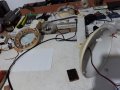
Here is my funky lamp:
20220312_204541.jpg
it has a magnifying glass and those are custom white power leds that I managed to repurpose into a larger circle for illumination, if you remember my older project, using a brown wood circle. It still works fine. Now I want to add 2 colored leds for the switch. To make it look more futuristic and scientific, you know? Haha.
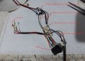
Read this photo red text explanations:
20220312_204556-b.jpg
and here is the (updated circuit, using 2x1n4148 diodes in reverse-paralel across each color LED:
20220312_204656.jpg
Now I burned another set of color LEDs.
20220312_204633.jpg
And this is my pink voltage divider made as always on cardboard, and it worked excelent with my DSO138 osciloscope to read the sinusoid of the mains voltage. Only that alone is a win for today. A win, because I managed not to burn anything important. I did measured everything before with my DMM and I was certain I will get small voltages from its pins onto osciloscope probes. I didnt guess it. I did it scientifically (this time). Haha.
I managed to glimpse a spike when switching, but because the speed was too fast, it was in a fraction of a second. On other speeds, no spikes whatsoever and I checked every permutation, but nothing. Only on fast speed it worked and only once (probably while the leds were not burned).
20220312_204621.jpg
Back to the problem in hand. - Lets add more protection to these LEDs !
Good ideas so far !
 
Last edited:
Status
Not open for further replies.
Top