Facebook
 Google
 GitHub
 Linkedin
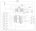
I am trying to make a series of electromagnets that cycle like an LED chaser. I am going to use it on a maglev model train. I am going to make a test track ten magnets long to make sure my concept will work and then I am going to make a track ~ 300 electromagnets long. I was thinking I would do this by taking an LED chaser circuit and replacing the LED with a NPN transistor like these https://www.adafruit.com/product/976?gclid=EAIaIQobChMIrbDKjp-L2gIVEJN-Ch3FUQ_-EAQYAyABEgIA8PD_BwE and wiring the electromagnets with that. I was going to use this power source https://www.amazon.com/dp/B01M3372K...olid=1BCVNFYS0SCVN&psc=0&ref_=lv_ov_lig_dp_it for the train and wire it so that the chaser circuit is wired low amps by placing a resistor before it. The collector on the transistor would be wired in parallel to the chaser so the chaser would have low eneough amps running through it but the electromagnets would have all two amps. Will this work or is there an easier way? Any help is appreciated. The goal is to have one circuit that will work at a length of around 10 but that can be extended to ~300 long effectively.
2 Amp Electromagnetic Chaser
- Thread starter William Schneider
- Start date