16 Rocket Semi-Simultaneous Launch Controller

Thread Starter

LydaRA

Joined May 6, 2021
37
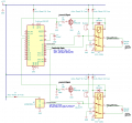
Trying to learn KiCAD....still rough, but getting better. Finally enough drafted to share (and drown in the red ink as you all mark it up)... Thanks in advance for constructive criticism! 1620717851007.png

Showing just two of eight independent parallel igniter sub-circuits. And considering variations....DPDT vs. SPDT....Arduino source current for continuity measurements vs. dedicated constant current source....building driver/relay sub-circuits vs. buying an 8x driver/relay board...

Obviously just focused on the pre-launch continuity tests and one the launch signal handling. There _ARE_ _MULTIPLE_ power discos, removable keys, momentary "deadman" switches, and program logic safety measures as well!
 
Last edited:

Thread Starter

LydaRA

Joined May 6, 2021
37
You canmake your gate to ground resistors and order of magnitude greater. Add a series gate resistor ~200 ohms.
Forgive me, where exactly, the MOSFETs? Or on the Arduinos? Certaily not on the constant current supply chip....which I realize is completely wrong as well.

And obviously the Arduino Uno doesn't have enough analog pins, but it was what KiCAD had in their library.
 

Thread Starter

LydaRA

Joined May 6, 2021
37
In your schematic are at least seven unconnected wires at +12V bus. This gives faulty PCB net.
Yes, I said this is a partial circuit.

Any other thoughts on the core topics of: 1) Three-state Continuity measurement or 2) Launch Signal handling?
 
Forgive me, where exactly, the MOSFETs? Or on the Arduinos?
You have the 10K pull down. That prevents the leakage current from triggering the MOSFETS, 100K should work,

You don't have a series resistor in series with the gate. There is a small amount of gate capacitance and a small value resistor limits the gate current spike.
 

Thread Starter

LydaRA

Joined May 6, 2021
37
Are you sure the HV9921 can work that way? As i know this is a switching regulator.
I think I prefer an isolated source of a constant "flashbulb safe" current for the continuity tests. Seems safer and frees pins on the Arduino. However there are a variable number of rockets to be launched, from eight (initial "drag race") down to possibly just one or two (after replacing igniters, re-clipping leads, correcting whatever misfires...). So with variable number of parallel paths, seems each continuity test sub-circuit will need its own low-voltage/low-current power source. Right? Any suggestions for a part number (I stuck in something representative, but KiCAD had just VAC chip....but yes, wrong item for this)?

Still think we'll need some sort of amplification to distinguish the three resistance levels on the igniter...
 
LT3092. You can parallel for more current. 200 mA max for one.

What's a typical ignitor resistance? If you use an LT6700 and say < 1 ohm. That chip has a 400 mV reference. So 400 mA/1 ohm is 400 mV. To use the comparitor at higher voltages, you use a voltage divider. If you wanted 10V, you would set your divider to give you 400 mV at 10V. If 400 mA is not a good number, then you may have to amplify.
 

Thread Starter

LydaRA

Joined May 6, 2021
37
LT3092. You can parallel for more current. 200 mA max for one.

What's a typical ignitor resistance? If you use an LT6700 and say < 1 ohm. That chip has a 400 mV reference. So 400 mA/1 ohm is 400 mV. To use the comparitor at higher voltages, you use a voltage divider. If you wanted 10V, you would set your divider to give you 400 mV at 10V. If 400 mA is not a good number, then you may have to amplify.
The spec on Estes' igniter is just 0.8Ohm at 12V. The cable from Pad Box to launchpad is max 15', 30' for the two-way trip....at 16gauge, still just 0.008Ohm. Not sure how much we'll pick up in the aviation connector (eight 16ga source pins plus one 10ga/four 16ga bonded for the return), or for the alligator clips onto the igniter.

Open should be easy to measure. But the difference between the expected resistance total versus the Short condition, should only occur at the igniter|clips....so just 0.8Ohm. If my first resister drops to just 100Ohm, the drop on the igniter is less than 0.1V! Of course you might have better design or math...
 
Open is easy as you said. It might be "easier" if you supply the current source with a regulated voltage. the voltage doesn;t have to be precise.

So, 15A to ignite, at 400 mA it probably won't ignite. To adjust, you would have to make sure both LT3092's are set to the same current if you use 400 mA.

If you use 200 mA or want it adjustible or easily adjustible, you would have to amplify. I think you would want to include the ignitor and wiring, not just the ignitor, so measuring the voltage at the board with 400 mA is probably the right thing to do. You can do a go/no go comparison at the board, but provide a voltage test point at the board level.
 

Thread Starter

LydaRA

Joined May 6, 2021
37
Open is easy as you said. It might be "easier" if you supply the current source with a regulated voltage. the voltage doesn;t have to be precise.

So, 15A to ignite, at 400 mA it probably won't ignite. To adjust, you would have to make sure both LT3092's are set to the same current if you use 400 mA.

If you use 200 mA or want it adjustible or easily adjustible, you would have to amplify. I think you would want to include the ignitor and wiring, not just the ignitor, so measuring the voltage at the board with 400 mA is probably the right thing to do. You can do a go/no go comparison at the board, but provide a voltage test point at the board level.
Yes, the measurement has to be done in the Pad Box--15' away from the igniter.
 

Thread Starter

LydaRA

Joined May 6, 2021
37
Well, thinking of "easier..."

I posted an electronic schematic of my model rocket launch controller system--in an Electrical Engineers' forum... And got back: "...use nails and 12v car battery."

Thanks, but I cannot imagine even trying to get that through the BSA's Program Hazards Analysis. Letting fourth and fifth graders dead short a car battery with nails cannot possibly be safer than even the sad OEM launch controllers.

Is _all_ public discourse really going the same dysfunctional, asinine way of politics???
 

Sensacell

Joined Jun 19, 2012
3,785
I am having a hard time understanding your schematics?

How does the ignitor get supplied with "firing" current? I see there is a buzzer in series with the "Auto-reset 5A fuse"?

A few thoughts in general:

1) Ground one side of the ignitor directly- this eliminates the relay contacts as a source of error / additional resistance in the firing circuit.
Nothing is gained by switching both sides.

2) You really want to detect 4 states - OPEN (no continuity) SHORT (leads touching) READY (correct ignitor resistance detected) and FAULT (voltage detected, firing pass switch SHORTED)
You really must anticipate a failure of the switching element that fires the ignitor, the WORST situation is a kid tries to connect an ignitor to leads that are live due to a failed switching element- and the rocket ignites in their face, this is actually quite likely to occur, relays get stuck, MOSFETs short...

Here is what I would suggest:

Use a switching regulator to create a lower voltage supply, (3.3 V) create a current source of around 100 mA, (a 30-ohm series resistor) connect this directly to the ignitor via a Schottky diode.
This creates a safe, energy-limited sensing current for detecting continuity- the diode switches this out when firing.

Use 3 comparators or an ADC to detect:

(A) Greater than 3.3V (FAULT - DANGER!!!)
(B) Greater than 80 mV (open)
(C) Less than 10 mV (short)

Fire the ignitor from the 12V rail with a high-side switch, with a 15A current limit, in software, limit the ON time to avoid overheat of the current limiting circuit.

(note the wrong resistor value in the diagram - should be 30 ohms)

Ignitor.jpg
 
Last edited:

djsfantasi

Joined Apr 11, 2010
9,237
Hi! I’ve been following this thread. The subject matter is of interest to me. I’ve only launched one rocket in my life, but always wanted to get into the hobby more actively. (The one rocket was my son’s. It came down on the roof of his middle school and was lost forever. His disappointment resulted in the end of the hobby for us).

I digress. I’ve been reading this thread and had the overwhelming feeling that we were making too much of this. I remembered the circuit being fairly simple. Let me know if you agree
F872B6B2-1FC0-4EA6-A231-AB02F2F50094.gif
The entire article can be found here. There is a discussion of all the features with solutions.
 

Thread Starter

LydaRA

Joined May 6, 2021
37
I remembered the circuit being fairly simple. Let me know if you agree
Yes, that's the classic, simple, SINGLE rocket launch controller circuit. We have several of these, made by Estes. We drag them out side-by-side-by-side... on tables and hand the keys to each Cub Scout.

But that leaves us managing 16 individual launch keys--in the hands of fourth grade children. I'm a good RSO, but we need better safety controls! The goal here is to introduce a RSO "Master Arm" and Countdown Clock that keeps everyone pressing their buttons at roughly the same time.

And because of the NAR Safety Code, launching more then ten at once requires us to put up to 300 feet between the launch pads and the Scouts/LCOs. Kind of hard to stretch the cheap 17' analog launch controllers' cables out that far... But if we collect those button push signals in an Arduino, then we can use RS485 to send those signals up to 1KM--using just three light-weight digital wires! Then have a second Arduino convert it back to the analog launch signal...

More complicated, sure....of necessity. But if NASA can do it... If NAR and Tripoli clubs across the country can do it... We are now in the "digital age," right?

I just need to get over the hump with the task of measuring the resistance states of the igniters!
 

Sensacell

Joined Jun 19, 2012
3,785
We are in the "Digital Age" but we still live in a very analog world.
You cannot program your way out of a poor analog design.

Focus on getting the "meat" of the matter right, then worry about the potatoes.

Note that #16 AWG wire is 4 milliohms per FOOT - 30 feet is 0.12 Ohms, this is about 15 % of your total igniter circuit resistance.
 
Use a switching regulator to create a lower voltage supply, (3.3 V) create a current source of around 100 mA, (a 30-ohm series resistor) connect this directly to the ignitor via a Schottky diode.
This creates a safe, energy-limited sensing current for detecting continuity- the diode switches this out when firing.

Use 3 comparators or an ADC to detect:

(A) Greater than 3.3V (FAULT - DANGER!!!)
(B) Greater than 80 mV (open)
(C) Less than 10 mV (short)
(A) Greater than 3.3V (FAULT - DANGER!!!) Schottky diode

I guess your saying you have a regulator issue at this point?

(a 30-ohm series resistor)

That resistor could be a metal oxide and effectively act as a fuse. What if 12V is supplied to this point? Or make it high enough power to handle 12V to ground?

(B) Greater than 80 mV (open)

R=80mV/100mA = 0.8 ohms? Isn't it 1.6 Ohms or something like that? You can;t use 3.3V because it's not 3.3 because of the diode. The contact resistances add to the 30 ohm resistor.

((C) Less than 10 mV (short)

R=10mV/100mA < 0.1 ohms. Huh?

Just general comments. The voltages that your trying to measure are too small. They would require amplification. The ripple from the switching regulator is on the order of the voltages your trying to measure unless you use a LT3042 regulator. https://www.analog.com/media/en/technical-documentation/data-sheets/3042fb.pdf There's lots of these on ebay and aliexpress.

It ALWAYS makes sense to to a force (Current) and measure (voltage) to measure low resistances. https://en.wikipedia.org/wiki/Four-terminal_sensing. The 30 ohm resistor is a poor current source.

Many comparitors and OP-amps in general are restricted to the amount of voltage they can see at their inputs. The Over the top (R) series of parts from Linear Technology/Analog Devices don't have that problem.

The LT6700 series of chips can have up to 36V at their inputs. There is an HV suffix. They are dual comparitors with a fixed reference of 400 mV and automotive qualified (Better for this application). You pick either both > or both < or <> by part number.

I don;t think the ripple from a switching regulator, schotkey diode and the voltages that need to measured are going to cut it.

So, my suggestion starts with a current source and tries to get the voltages out of the noise floor.
Dual-slope A/D conversion is probably not a bad idea and the question is can you even do it with an A/D converter and multiplex the reading of voltages or would you want to. Is redundancy important? Is leaving the computer out of the equation for that part better?

The reason for using a voltage regulator before the current regulator although it's probably not required, but it EASIER to test fr an open. 400 mA is out of the noise floor.

Here https://www.analog.com/en/technical...ut-impedance-with-inputs-driven-apart-or.html is a blurb to look at. There is a differential amplifier with a gain of 100 in this note, but it requires a +-5V supply.

Op-amps without power and with voltages at it's inputs are something you have to protect against.

So, I'm guessing you want open, in range and short.
Open seems easier to do of the max voltage is known. And better yet, if the voltage is regulated below what would cause ignition.
I definitely liked the idea of limiting the firing time.

Adjustable, is probably not a good idea unless it's done in software. Providing a test point for the voltage measuring portion is a possibility. Even if you do have separate, independent circuits not tied directly to the computer operating, you can still multiplex the "differential" voltage readings.

My boss said that people like to see numbers between 1 and 10 which is why I really hate the unit of kilopascals for pressure.
3000 Psi or typical tank pressures is like 21,000 kPa. %full is probably a better number.

So, if you have a display, you could display % nominal resistance or "Power expected"
 

Sensacell

Joined Jun 19, 2012
3,785
(A) Greater than 3.3V (FAULT - DANGER!!!) Schottky diode

I guess your saying you have a regulator issue at this point?

No, this is to detect a short in the high side switch, a fail-safe measure.
How do you keep a stuck relay from causing a rocket engine to go off in a kid's face?
By checking that there is less than 3.3 V on the output leads.


(a 30-ohm series resistor)

That resistor could be a metal oxide and effectively act as a fuse. What if 12V is supplied to this point? Or make it high enough power to handle 12V to ground?

The series diode blocks any current flow when the 12V turns on.

(B) Greater than 80 mV (open)

R=80mV/100mA = 0.8 ohms? Isn't it 1.6 Ohms or something like that? You can;t use 3.3V because it's not 3.3 because of the diode. The contact resistances add to the 30 ohm resistor.

A more detailed analysis: The ignitor is supposed to be around 0.8 Ohms, the wire leads about 0.12 ohms...
3.3V minus a Schottky drop is around 2.8V / 31 ohms = 90 mA.

Max voltage with good ignitor = 83 mV.

Shorted leads = 10.8 mV. (wire resistance alone)


((C) Less than 10 mV (short)

R=10mV/100mA < 0.1 ohms. Huh?

Just general comments. The voltages that your trying to measure are too small. They would require amplification. The ripple from the switching regulator is on the order of the voltages your trying to measure unless you use a LT3042 regulator. https://www.analog.com/media/en/technical-documentation/data-sheets/3042fb.pdf There's lots of these on ebay and aliexpress.

We need to keep the measurement current well below the ignition current so a lower value is called for, and yes - it will require amplification.
Regulator ripple will be diluted by the ratio of resistances - to about 1/30th of the regulator output- no problem there.


It ALWAYS makes sense to to a force (Current) and measure (voltage) to measure low resistances. https://en.wikipedia.org/wiki/Four-terminal_sensing. The 30 ohm resistor is a poor current source.

Poor current source indeed, but why do we care? The thresholds will be stable, but not perfectly linear, a high-quality current source is not needed unless we need to MEASURE resistance, rather than just THRESHOLD resistance.

Many comparitors and OP-amps in general are restricted to the amount of voltage they can see at their inputs. The Over the top (R) series of parts from Linear Technology/Analog Devices don't have that problem.

To protect the opamp, just use a 10K series resistor and a diode to clamp the signal to the 3.3 V supply, then it's bulletproof.
If you read 3.9 volts, you know the high side is shorted (3.3V plus a diode drop)

I would use a rail-to-rail opamp with a 200 mV negative supply generator (LM7705) to allow operation all the way to ground.


The LT6700 series of chips can have up to 36V at their inputs. There is an HV suffix. They are dual comparitors with a fixed reference of 400 mV and automotive qualified (Better for this application). You pick either both > or both < or <> by part number.

I don;t think the ripple from a switching regulator, schotkey diode and the voltages that need to measured are going to cut it.

So, my suggestion starts with a current source and tries to get the voltages out of the noise floor.
Dual-slope A/D conversion is probably not a bad idea and the question is can you even do it with an A/D converter and multiplex the reading of voltages or would you want to. Is redundancy important? Is leaving the computer out of the equation for that part better?

The reason for using a voltage regulator before the current regulator although it's probably not required, but it EASIER to test fr an open. 400 mA is out of the noise floor.

Here https://www.analog.com/en/technical...ut-impedance-with-inputs-driven-apart-or.html is a blurb to look at. There is a differential amplifier with a gain of 100 in this note, but it requires a +-5V supply.

Op-amps without power and with voltages at it's inputs are something you have to protect against.

So, I'm guessing you want open, in range and short.
Open seems easier to do of the max voltage is known. And better yet, if the voltage is regulated below what would cause ignition.
I definitely liked the idea of limiting the firing time.

Adjustable, is probably not a good idea unless it's done in software. Providing a test point for the voltage measuring portion is a possibility. Even if you do have separate, independent circuits not tied directly to the computer operating, you can still multiplex the "differential" voltage readings.

My boss said that people like to see numbers between 1 and 10 which is why I really hate the unit of kilopascals for pressure.
3000 Psi or typical tank pressures is like 21,000 kPa. %full is probably a better number.

So, if you have a display, you could display % nominal resistance or "Power expected"
 
Top