16 Rocket Semi-Simultaneous Launch Controller

KeepItSimpleStupid said:
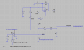
Would you want to put an LED and resistor across the relay coil?

Maybe, but only helpful diagnosing when looking inside the box. So maybe not spend the power?

10*5mA or even 1mA. Standard LED is 20 mA. It's not a lot, but it's on during ignition. Put one in with a remveable shunt or switch so you have it for debugging with or without a 1.9 ohm resistor attached.
 
KeepItSimpleStupid said:
Make the input to U7 a voltage source like the LT3042, so you can more easily detect open.
Huh? Sample? Getting a _lot_ of complaints from others about the dedicated "flashbulb safe" constant current supply. I've never used one, but seems better than pulling too much from the Arduino.

Again, assuming using a comparitor and not an A/D converter. What you really want to know is the voltage across the current regulator. That determines an open. You can do that with a multiplexor. Look at the ignitor voltage or the voltage across the current regulator.

If the input of the LT3092 was known to be say 8V, then say > (8-1.2) is open. Don't know the numbers. You have a FIXED voltage to look for.
 

Sensacell

Joined Jun 19, 2012
3,785
You need to wrap your head around this resistance measuring concept.

Adding resistance in the circuit (those pots) dilutes the ability to detect what you are really trying to measure. The voltage that you read is = I*R,
the sensing current multiplied by the resistance of the circuit. The voltage across a good ignitor is 0.025 A * 0.8 ohms. = 0.02 Volts, adding extra resistance just adds additional voltage drop that dilutes what you are trying to measure, making it more difficult to differentiate between good and shorted conditions.
 
KeepItSimpleStupid said:
the app note earlier had a differential amplifier which you can use. You cab use an LM7705 https://www.ti.com/product/LM7705 to generate a slightly negative power supply voltage, so you can get 0V out for 0V in. You can put your differental amplifier at pins 4 and 9 of the relay with resistors to ground to sink the bias current.

At least when 0 is at mid supply, you can read small voltages better.
Huh? Sample? Not sure I follow.

There are some real world issues. You can get close to ground, but you can't get 0V out UNLESS you have a negative voltage. The LM7705 generates a "slightly negative" voltage, so yu can achieve 0V out.

There is the input bias current < say a few nA or smaller. Just like the FET (100K), you have to provide a place for it to go, otherwise unconnected means a big output over a short time.

There is an input offset voltage which you can compensate for. Vos and Ib are temperature dependent parameters.
Vos gets amplified, so it's (Vin+Vos)*Gain

Your dealing with small voltages. Vos could be important here.

An op-amp with a +-5 supply or -200 mV and +5 is generally OK, because you may be able to get 0V out. You won;t get 5V out. Just slightly less.

take an automotive sensor such as this one: https://www.digikey.com/en/products/detail/nxp-usa-inc./MPX2100DP/684661

The output is "ratiometric". When it uses 5V in the calculation, it isn't 5V. It could be 4.9 to 5.1 V and it;;s the instantaneous value at the time of measurement. The A/D effectively measures a percentage of Vcc.
The zero could be artifically moves to around 1/2 the supply voltage. You can then measure +-Volts from this artificial zero.

The sensor might say 0-5V output, but it isn't when you look at the details. 0 and 5V are not achieveable.

A single supply OP-amp that operates on 5V is not uncommon.
 
KeepItSimpleStupid said:
Would an encoder be neccessary? or have that sort of information done at the master CPU?
Huh?

An encoder allows you navigate a menu without a keyboard. It contains maybe 16 clicks over 360 degrees. You read a bi-phase signal, so you can determine direction. You can push it or push and hold it. Some even have a cler knob with a bi-color LED's.

example: https://www.sparkfun.com/products/15083

You could set the nominal ignitor resistance for instance.
 
Never dealt first hand with a VAX, but the instruction set was complex and impressive. Ethernet was a foreign concept. My Forte was a PDP 11/20, PDP 11/50, the 11/2 and the 11/23+
 
Sensacell said:
The continuity voltage straight to the Arduino? The continuity voltage is too low to be measured by the ADC correctly.
The ADC inside the ATMEGA168 is 10 bits, if the full-scale range is 5V, each bit represents 0.0048 Volts, a "good" ignitor will read only 12 counts, out of 1024...
That's my real fear. I keep hoping against hope that someone will contribute an example circuit that helps solve this!

You measure differentially and amplify. You use a low noise power supply and you SHIFT 0 to the center scale where +-1 bit doesn't matter much anymore.

It's also why I;m suggesting NOT to use the internal A/D, but to use an A/D that uses the dual-slope conversion method, The same method that your DMM likely uses. In an inside a building environment, the integration time is set to an integer number of power line cycles. The dual-slope converter wont be sensitive to power ripple from a switching regulator.

This isa battery device and you want, but don't want a linear regulator. You may want a low noise efficient regulator. LT3092?
 
Totall agree with @Sensacell. You can't put resistors in the path your tryng to measure. If you want to change the nominal ignitor resistance, do it with an encoder HMI and display. It's also why I suggested % nominal value for a display.
 

Sensacell

Joined Jun 19, 2012
3,785
Let's go back to fundamentals.

1) The more current that flows through the resistance we want to measure, the larger the signal, it is always best to start with the largest signal you can.
If Estes corporation and their teams of lawyers say 50 mA is ok, use that value. Why make the signal smaller?

2) The physical connections:
Eliminate any source of measurement uncertainty- uncontrolled contact resistances can cause measurement errors.
Get that relay out of the equation, it isn't helping you here. There is no need to switch between "measure" and "fire" circuits, it's trivial to make them co-exist simply.

3) Current source- let's examine this idea and see what's really needed.
Assuming we want 50 mA flowing:

Let's look at the difference between using a single cheap resistor, or a complex and expensive precision current source.

First, the precision current source:
Shorted leads ( 0.12 ohms) = .05A X 0.12 ohms = 6 mV.
Good ignitor (.8 ohms + leads = 0.92 ohms) = 0.05A X 0.92 = 46 mV.

Now let's look a using a 5V source and a humble resistor in series.
5 volts / 50 ma = 100 ohms.- we use a 100 ohm resistor.

Shorted leads ( 0.12 ohms) current = 5/100.12 ohms = 0.04994007 A, plugging that current in we get 0.04994007A X 0.12 ohms = 5.9928 mV.
Good ignitor (.8 ohms + leads = 0.92 ohms) 5/100.92 ohms = 0.04954419 A, plugging that current in we get =0.04954419 X 0.92 = 45.5807 mV.

The difference is microvolts, totally trivial.
Cost and complexity? you decide.

4) Differential measurements?
The current through the ignitor returns to ground, what are you going to 'difference'? besides the tiny voltage drops inside your box?
This makes sense if you are going with a 4-wire Kelvin measurement, but that's total overkill here.

Just go with a simple single-ended amp to boost the signal up into a range where the ADC you already have has enough bits to make a reasonable differentiation.
 

Thread Starter

LydaRA

Joined May 6, 2021
37
I kinda got the idea of each kid has a launch controller which is some distance away from the rocket and then some sort of firing thingy, like a dental x-ray or "nurse call" button some distance away.

with maybe large countdown display(s) that everyone could see.
Yes, we currently use the OEM controllers, just 17' of cable... 1620924834897.png

This new system will act as an extension, with added features to boot!

The battery for 10 ignitors. lets use 2 ohms. 2|2 2|2 2|2 2|2 2|2 = 1|1| 1|1 |1 or 0.5|0.5 | 1 or 0.25 | 1 or 0.33 ohms

12/0.33 = 36 instantaneous amps. here https://docs-emea.rs-online.com/webdocs/0b5b/0900766b80b5b643.pdf is a typical SLA battery, It can deliver 180 A for 2s and it has an internal resistance of 14mΩ. Your wire resistance will be dominant.

Now, I suppose you would want to keep the battery away from the rockets and protected. What's a typical spacing of the rockets?

How many times on a charge do you intend to launch?
We'll have the battery in the Pad Box, on the ground at the end of a "saw horse" holding the launchpads. Allowed 2' from box to leg, and then 3' up the leg, then rockets spaced one per foot.

We launch about 40 to 80 rockets per hour. Launch every hour for 8-10 hours in a day. Then we could re-charge overnight. Or run for 4-5 days over two weeks, then back to storage.
 

Thread Starter

LydaRA

Joined May 6, 2021
37
1) The more current that flows through the resistance we want to measure, the larger the signal, it is always best to start with the largest signal you can.
If Estes corporation and their teams of lawyers say 50 mA is ok, use that value. Why make the signal smaller?
Ok, good point. And it's 20-40 times less than the recommended "all-fire" current anyway.

2) The physical connections:
Eliminate any source of measurement uncertainty- uncontrolled contact resistances can cause measurement errors.
Get that relay out of the equation, it isn't helping you here. There is no need to switch between "measure" and "fire" circuits, it's trivial to make them co-exist simply.
So dumping 12V 2A into the igniter, while still connected to the mere 5V 40mA Arduino pins? Multiplied by 8-10 parallels going at once? How does 33A not let the smoke out of the Arduino?

3) Current source- let's examine this idea and see what's really needed.
Assuming we want 50 mA flowing:
Now let's look a using a 5V source and a humble resistor in series.
5 volts / 50 ma = 100 ohms.- we use a 100 ohm resistor.

Shorted leads ( 0.12 ohms) current = 5/100.12 ohms = 0.04994007 A, plugging that current in we get 0.04994007A X 0.12 ohms = 5.9928 mV.
Good ignitor (.8 ohms + leads = 0.92 ohms) 5/100.92 ohms = 0.04954419 A, plugging that current in we get =0.04954419 X 0.92 = 45.5807 mV.

Just go with a simple single-ended amp to boost the signal up into a range where the ADC you already have has enough bits to make a reasonable differentiation.
Makes sense. So we need to amplify the measurement by 100 to maximize the Arduino's 5V analog input to more easily "see" 0V versus 0.5V versus 4.5V? Need to nail down the 12V to 5V step-down part, the 100x amp, and how to wire it up...

Thanks.
 

Sensacell

Joined Jun 19, 2012
3,785
Ok, good point. And it's 20-40 times less than the recommended "all-fire" current anyway.


So dumping 12V 2A into the igniter, while still connected to the mere 5V 40mA Arduino pins? Multiplied by 8-10 parallels going at once? How does 33A not let the smoke out of the Arduino?
The circuitry 'samples' the voltage on the ignitor, almost no current flows into this sampling circuit. None of the firing current flows through the Arduino.
A simple protective clamp circuit protects the amplifier from overvoltage. When the ignitor fires, the amplifier output just saturates, going to the 5V rail.


Makes sense. So we need to amplify the measurement by 100 to maximize the Arduino's 5V analog input to more easily "see" 0V versus 0.5V versus 4.5V? Need to nail down the 12V to 5V step-down part, the 100x amp, and how to wire it up...

Thanks.
Here is an idea for the circuit.

It uses the 5V to generate a sensing current via R1, the diode D1 prevents any reverse current flow when the 12V FIRE voltage is applied.
I added an extra concept: the output voltage cannot go over 4.8 V when measuring continuity, but R9 and D3 make it go all the way to 5V when a firing voltage is detected.
You can verify that the entire circuit is working, and flag any faults just by monitoring the ADC voltage.


Note that you MUST use a good rail-to-rail opamp here! a garden variety opamp like the LM741 will NOT work.
The Mircrochip MCP6024 would be a good choice, 4 opamps in one package.
 

Attachments

Top