15V PSU-First project

Thread Starter

ISB123

Joined May 21, 2014
1,236
Hello,
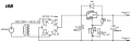
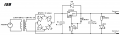
This is the first project I made by myself,I would like to know would this circuit actually work and if I made some mistakes.
Diode bridge is built with 4xBY255 Diodes.Capacitors is Electrolyte and one Ceramic,they are used to smooth out the wave that we get from diodes.
LM350 is programmed by R1 910Ω resistor and 10KΩ POT.
My idea is to get aprox. 15V(14.98) when POT is at its maximum resistance value.

If everything is OK then I would continue to designing a PCB and ordering parts next month.
Cheers!

High res. image:
http://i.imgur.com/F4S4EIr.png
 

Attachments

ronv

Joined Nov 12, 2008
3,770
D1 and D# should be reversed. You will need a large filter cap in addition to C1 to smooth out the ripple. Since your current is fairly low (1/2 amp?) you could use an LM317 regulator and save some $$. You should redo the voltage set resistors if you do that - check the 317 data sheet. In either case you will need some heat sink. You might also save some money by using a 16 volt transformer.
 

THE_RB

Joined Feb 11, 2008
5,438
And there should be a cap between pins 2 and 3 of the pot. Failure to put a cap there means that any "scratchy" behaviour of the pot results in high power noise at the PSU output.

On top of all the other good points the LED on the variable output is not a good idea. It may fail to light up when the pot is at minimum and may be too bright when the pot is at maximum. If that is a power indicator LED it is better to put it before the voltage regulator.
 

Thread Starter

ISB123

Joined May 21, 2014
1,236
Hello,here is the "improved" schematic.I decided to scrap the LED power indicator since the resistor Wattage would have to be pretty big and it would cost to much if someone has better idea I would like to hear it.I changed the transformer to more cost efficient one.
Thanks for helping!
 

Attachments

MikeML

Joined Oct 2, 2009
5,444
Why the 1000uF on the output? You would do better with 2000uF at the input of the '350, and use only the recommended bypass to improve HF regulation (see data sheet) at the output?

Oh, and C3 needs to bypass the entire rehostat, not the wiper as you show it. You have a missing connection from the wiper (pin 2) to the top end of the pot (pin 1)?
 

Thread Starter

ISB123

Joined May 21, 2014
1,236
What Wattage rating should I use on my resistors?

PS

3W should be enough?
 
Last edited:

MikeML

Joined Oct 2, 2009
5,444
What Wattage rating should I use on my resistors?

PS

3W should be enough?
How about 1/4W?

It ain't rocket science...

P = e^2/R

For R1, the reference voltage is 1.25V, so 1.25*1.25/91 = 0.017W

For the pot, the current is just a bit more than the current through R1, which is I=E/R = 1.25/91 = 14mA

So the max voltage across the Pot is E=IR = 0.014*1000 =14V

therefore the power is E*I = 14*0.014 = 0.194W
 

Thread Starter

ISB123

Joined May 21, 2014
1,236
Thanks,I was inputting 15V in the formula while I should been inputting ref. Voltage.So that was the reason I was getting funky wattage.Now one last question.If I were to use 18V 18VA transformer it would give me 1amp,the problem is I can only find 18V 3VA trans. So are those with smaller VA pretty much useless?
 

ronv

Joined Nov 12, 2008
3,770
Since the order form is still blank I would consider a couple more things.;)
Potentiometers often have poor tolerances (+/- 10 or 20% is not uncommon) so I think I would use a 2k pot and 150 ohm resistor so you can be sure to reach 15 volts.
Don't forget the transformer voltage is RMS but the voltage after filtering is peak.
Here is a little write up on how to select transformer and filter size.
http://waynestegall.com/audio/ripple.htm
Have you picked a heat sink for the regulator yet? A lot of people think because the data sheet says 3 amps that no heat sink is required, but at lower voltage settings the power in the regulator can be much to high to run without a heat sink.
 

KLillie

Joined May 31, 2014
137
Just checked the specs on lm350, D5 and D6 are to protect the voltage regulator from shorts that may result in the capacitors discharging into the IC.
 
Last edited:

ronv

Joined Nov 12, 2008
3,770
Here is a 16 volt one that is reasonable:
http://www.mouser.com/ds/2/410/VPL16-600-224041.pdf

So lets look at the numbers.
16 X 1.414 = 22.6 volts - 10% low line = 20.3 volts. Minus 2 diode drops 18.7 volts.
minus 2.5 v ripple voltage = 16.2 volts. Minus 1.8 volts for the regulator at 1/2 amp. = 14.4 volts. Hmmm, doesn't quite make it.:(
So lets use a little better diode say SB140.
http://www.mouser.com/ds/2/427/88715-108282.pdf
Now we have 15.05 minimum. Maybe to close. so lets make the cap a little bigger. Say 2700 Ufd. Now we only have 1.85 volts of ripple so we should be able to get to 15.7 volts in good shape even if the line voltage is low.
 

Thread Starter

ISB123

Joined May 21, 2014
1,236
Everybody who has 80's radio and doesn't care about it should open that thing up and take all the parts unless they are damaged.I opened one radio and it had 80% of stuff I wanted for my projects :D.
 

Thread Starter

ISB123

Joined May 21, 2014
1,236
Finished! Took 3 days mostly because the damn case never looked right so I had to remake it 2 times.
Has a voltmeter module seems to be pretty accurate,only need to add fuse.Could I use car fuse(3A) since I don't want to pay shipping for a single fuse.

240V/50Hz to 34V/1A


bance

Joined Aug 11, 2012
315
Congratulations, your first project I take it?

Now you need to start to think how you can improve it... Maybe start with using a single plug to power it?

good luck Steve.

PS get some fire insurance.
 
Top