12v wiring electric motors and lock assembly

Thread Starter

Aauto12v

Joined Jul 4, 2024
9
Need help with a 12v Automotive application project.

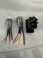
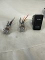
2 12v electric motors
2 12v Relays
1 electric latch/lock assembly
2 push button switches

I built a custom storage compartment with electric motor to automatically open and close and I added an electric latch/lock assembly that locks when the lid is closed. The electric motor wiring setup is 2 separate push buttons, one to open and other to close. Each push button must be pressed until the lid opens or closes.

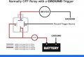
I want to wire the open push button for the electric motors when pressed, simultaneously to trigger the release of the lock/latch assembly,

My concern is when the push button is held for a period (until it fully opens, 7-8 seconds) it can damage the lock/latch assembly.

The lock/latch only needs a quick 12v power impulse (5-10 amps) to release.


Any ideas or suggestions?
 

Thread Starter

Aauto12v

Joined Jul 4, 2024
9
Thank you for reply.
Current wiring , 2 push button , 2 relays, 2 motors.

Lock/latch no wiring setup yet.

Do I need to setup new power connection
With relay for the lock ? Then add your wiring setup , connecting to the open push button.
 

LowQCab

Joined Nov 6, 2012
5,101
A Schematic-Diagram of what You already have,
and a full description of the Power-Supply that You are thinking of using,
( hopefully, this will be easily interpreted from the Schematic ).

If You want, I can create an all Electronic Schematic, without Relays,
but it will require the "Locked-Rotor-Current", or, "Stalled-Current", specification of your Open/Close-Motor.
If Locked-Rotor-Current is not known, figure that the Locked-Rotor-Current is ~4X the full-Load-Current.

A link to the Motor that You want to use would be very useful.
At least provide pictures.

Relays are more simplistic, but You won't learn as much as You would building an all Electronic-version.

In either case, "Travel-Limit-Switches" are highly recommended, unless your Motor is exceptionally weak.
.
.
.
 

Thread Starter

Aauto12v

Joined Jul 4, 2024
9
Thank you for your reply and help, really appreciated. For clarification I will add more details.
The power supply is 12vdc car battery 800amp. It will take sometime to create a diagram, I will work on it.
But I do have a drawing I did that can simplify this setup. The current setup basic components are 2 12vdc motors and 2 relays and 2 push buttons. All in one harness. Open button controls both left and right 12vdc motors to turn one direction to open. The Close buttons controls both left and right 12vdc motors to turn opposite direction to close. This is already working and functioning with all the fuses and relays, purchased it complete. I don't have information on the ampage for the 12vdc motors. The look like car window motors. The part of the harness that connects to the power supply has a 12volt sealed relay, 40amp sealed fuse receptacle that connects to the main 12v battery, and 15amp fuse that goes in the fusebox, this for both 12vdc motors.

I just want to add in the electric lock/latch assembly. It's actually 2 latches that we will wire together. Im not sure the exact amp/volt, but it needs at least 12v-3amps per lock.

Can we create a wiring setup that taps into the existing "open" push button or relay? We don't need the "close" push button side. See attached drawing with the wiring setup for the existing "open" side. and I added the 2 locks icons for reference.
 

Attachments

LowQCab

Joined Nov 6, 2012
5,101
Now that I can see that You are switching the "Hot" with your Push-Button ..............

Since You have stated that the Current requirements of
the "Latch-Solenoid" are "between ~5 and ~10-Amps"
then there needs to be an additional Relay added to Provide Power to operate it,
complete with it's own separate ~10-Amp-Fuse.

My Circuit is superfluous, and excessively complex in this case.

Simply connect a 1000uF, 35-Volt Electrolytic-Capacitor from the "Open" Push-Button
to the Coil of the new Relay, ( terminal #85 ),
and then Power the Latch-Solenoid directly with the new Relay.
Positive-Terminal of the Capacitor to the Push-Button.

The new Relay will stay "On" for less than half a Second when the "Open" Push-Button is pressed.

I just noticed your latest Post.
That doesn't look like a Solenoid activated Latch, it probably has a Motor in it.
that means that it may or may not have a "Spring-Return" to the Latched-Position.
This may complicate things quite a bit.
You'll have to get this Latch in your hands and manually power it to see how it operates.
If it requires a reversal of polarity to return to the "Latched" state,
it will require some additional Components to make that happen
.
.
.
 
Last edited:

Thread Starter

Aauto12v

Joined Jul 4, 2024
9
Now that I can see that You are switching the "Hot" with your Push-Button ..............

Since You have stated that the Current requirements of
the "Latch-Solenoid" are "between ~5 and ~10-Amps"
then there needs to be an additional Relay added to Provide Power to operate it,
complete with it's own separate ~10-Amp-Fuse.

My Circuit is superfluous, and excessively complex in this case.

Simply connect a 1000uF, 35-Volt Electrolytic-Capacitor from the "Open" Push-Button
to the Coil of the new Relay, ( terminal #85 ),
and then Power the Latch-Solenoid directly with the new Relay.
Positive-Terminal of the Capacitor to the Push-Button.

The new Relay will stay "On" for less than half a Second when the "Open" Push-Button is pressed.

I just noticed your latest Post.
That doesn't look like a Solenoid activated Latch, it probably has a Motor in it.
that means that it may or may not have a "Spring-Return" to the Latched-Position.
This may complicate things quite a bit.
You'll have to get this Latch in your hands and manually power it to see how it operates.
If it requires a reversal of polarity to return to the "Latched" state,
it will require some additional Components to make that happen
.
.
.
Regarding the latch, there is small motor inside that only activates to release the lock. So you would manually close the lid and the striker lands inside the latch and it locks (no electricity) (spring/lock). The motor operates only to release lock.

I was looking at my notes and I may have confused the relay wiring. I will double check and get back.
But see if this makes sense to you or not.
Based on last notes, when examining wires and connections, Relay and battery.
Summary:
Push button switch pin "NO" was wired to 85
Push button switch pin "C" was wired to 87a
Relay pin 87a wired to Ground
Relay pin 87 wired to Battery
Relay pin 87 wired to both 12vdc motors
Relay pin 86 wired to 12vdc Battery
Relay pin 30 wired to a fuse and to 12vdc Battery
Also. the Push button is an LED. The Push button Positive pin is wired to 87a.The Push button negative pin is wired to 87.

Again I will confirm if these notes are correct. Sorry for the confusion. All this is new to me.
 

LowQCab

Joined Nov 6, 2012
5,101
If your PDF Schematic is accurate, everything is fine.
If Your description of the operation of the Latch-Motor is accurate, everything is fine.
Just add a second "Open" Relay, and power it's Coil through a large Capacitor.
You may need to experiment with a larger-Capacitor, or adding a second identical Capacitor,
if the "On-Time" is too short for the Latch-Motor to operate fully.
.
.
.
 

Thread Starter

Aauto12v

Joined Jul 4, 2024
9
Regarding the latch, there is small motor inside that only activates to release the lock. So you would manually close the lid and the striker lands inside the latch and it locks (no electricity) (spring/lock). The motor operates only to release lock.

I was looking at my notes and I may have confused the relay wiring. I will double check and get back.
But see if this makes sense to you or not.
Based on last notes, when examining wires and connections, Relay and battery.
Summary:
Push button switch pin "NO" was wired to 85
Push button switch pin "C" was wired to 87a
Relay pin 87a wired to Ground
Relay pin 87 wired to Battery
Relay pin 87 wired to both 12vdc motors
Relay pin 86 wired to 12vdc Battery
Relay pin 30 wired to a fuse and to 12vdc Battery
Also. the Push button is an LED. The Push button Positive pin is wired to 87a.The Push button negative pin is wired to 87.

Again I will confirm if these notes are correct. Sorry for the confusion. All this is new to me.
Based on you
Regarding the latch, there is small motor inside that only activates to release the lock. So you would manually close the lid and the striker lands inside the latch and it locks (no electricity) (spring/lock). The motor operates only to release lock.

I was looking at my notes and I may have confused the relay wiring. I will double check and get back.
But see if this makes sense to you or not.
Based on last notes, when examining wires and connections, Relay and battery.
Summary:
Push button switch pin "NO" was wired to 85
Push button switch pin "C" was wired to 87a
Relay pin 87a wired to Ground
Relay pin 87 wired to Battery
Relay pin 87 wired to both 12vdc motors
Relay pin 86 wired to 12vdc Battery
Relay pin 30 wired to a fuse and to 12vdc Battery
Also. the Push button is an LED. The Push button Positive pin is wired to 87a.The Push button negative pin is wired to 87.

Again I will confirm if these notes are correct. Sorry for the confusion. All this is new to me.

Which pin on the “open” push button
“NO” or “C” to the Capacitor + pin. ?

Can you provide the Relay diagram for the 2 lock/Latch wiring.
Showing which relay pins to battery , ground latch, push button. Etc.
 

LowQCab

Joined Nov 6, 2012
5,101
Sorry for Steam-Rollering You, this must be brand-new for You.

So far, I've only seen a partial Schematic, and I just assumed that You had the rest of it all under control.

Do your "Open/Close" Motors have only 2-Wires ?, or more than 2-Wires each ?
If these are Windshield-Wiper-Motors, they could have multiple-speeds,
and various special switches for "Parking" the Blades, etc.
If they are Electric-Window-Motors, this is highly unlikely, but still a possibility.

Exactly how the Motors must be wired to achieve reliable
Forward and Reverse-operation has to be established first.

Actually, I was surprised to see You wanting to use a very expensive Merc Trunk-Latch-Mechanism.
so this whole project may be larger and heavier than I first imagined.

So this brings-up the subject of the mechanical-aspects of the Project.
It won't do any good to do the "figure-out" on the Electrical-Controls if it won't work-out mechanically.

Limit-Switches may be required.

PICTURES ARE REQUIRED.
.
.
.
 

Thread Starter

Aauto12v

Joined Jul 4, 2024
9
Sorry for Steam-Rollering You, this must be brand-new for You.

So far, I've only seen a partial Schematic, and I just assumed that You had the rest of it all under control.

Do your "Open/Close" Motors have only 2-Wires ?, or more than 2-Wires each ?
If these are Windshield-Wiper-Motors, they could have multiple-speeds,
and various special switches for "Parking" the Blades, etc.
If they are Electric-Window-Motors, this is highly unlikely, but still a possibility.

Exactly how the Motors must be wired to achieve reliable
Forward and Reverse-operation has to be established first.

Actually, I was surprised to see You wanting to use a very expensive Merc Trunk-Latch-Mechanism.
so this whole project may be larger and heavier than I first imagined.

So this brings-up the subject of the mechanical-aspects of the Project.
It won't do any good to do the "figure-out" on the Electrical-Controls if it won't work-out mechanically.

Limit-Switches may be required.

PICTURES ARE REQUIRED.
.
.
.
Yes it’s all new for me, But learning quickly.
The open/close motors have 2 wires each. Forward and reverse. They operate at same time when push buttons activate. Mechanically it’s working well. There are limit switches as well.
 

LowQCab

Joined Nov 6, 2012
5,101
You've got to be able to articulate all this info in a manner that anyone dealing with
Electronics can readily understand,
this is the language of the Schematic-Diagram.

Unfortunately, Schematics still contain a little bit of the "Wild-West", and are not strictly regulated in any way.
But still, if You plan to do much more stuff with Electronics, it would be worthwhile to learn to create a Schematic.
.
.
Motor Reversing Push-Buttons .png
.
Motor Reversing Push-Buttons 2 FLAT .png.
Chicken Door .png
.
 

Thread Starter

Aauto12v

Joined Jul 4, 2024
9
Hello again. Need some more help.
I used the attached diagram for the Lock/latch wiring using a 4pin relay with a ground trigger. Does this look fine.
Also my next step is to re-wire the existing 2 Push LED button switches to the motors ( Open and close). I want to re-wire them to a single rocker switch (open/close) 3 pins.

each push button has 4 wires connected.
positive, negative , NO, COM.

the rocker switch has 3 pins.
Then I want to connect the lock/Latch with the capacitor to the open button for release activation.

can you help with direction and diagram.
 

Attachments

Top