0.9mV is what I read as well. However, most meters will read that much voltage without being connected to anything. At that low voltage I'd call it zero volts, or at least approaching zero volts.
Right now I suggest making a direct connection between the two trigger terminals of the timer and see if it still triggers.
My guess is that it is looking for a contact closure to start timing, not a voltage. So I suggest reading the instructions again, very closely. Then disconnect the wire and see if it starts timing when the power is switched on. The problem does not make sense any more.
This sparks a thought: On chips like a quad NAND gate (and many many others) you want to tie all unused inputs either high or low. Leaving an input floating leads to oscillation that can destroy a chip. I think the resistor idea is probably well suited, providing I have an understanding of this thread thus far. Don't shoot me (or at me) if I'm wrong.
OK, I went and ran some more tests. Again, the transistor in photo is a place-holder (not there). The purple wire, spliced off from motor, I am seeing a voltage of under 1v when I press "DOWN" button on the Rocker switch. I want an "open-circuit-state" going into contact#3 since as-of-now the A103-006 is counting in seconds (although I expected it be 'off'). what is best to create an "open-circuit-state" ? Reminder of A103-006 Specs:
{Timing Start Input: NPN Signal or Contact Closure; Low State: < 1.0 VDC, High State: > 2.0 VDC } Please advise further. thanks
The simplest way to start the timer when the winch is driven in the "Pay Pout" direction will be to use a single relay with a diode in series, connected in parallel with the motor, with the polarity of the diode set so that the relay operates and starts the timer when the "unwind" rotation is selected. Only two components, and easy to mount 12 volt relays are commonly available, 24 volt relays also available but not as common. And a cheap one amp 100 PRV diode, such as a 1N4001, or similar, would be all that is required. Simple, Cheap, and very easy to understand. And no modifications to the present system.
The simplest way to start the timer when the winch is driven in the "Pay Pout" direction will be to use a single relay with a diode in series, connected in parallel with the motor, with the polarity of the diode set so that the relay operates and starts the timer when the "unwind" rotation is selected. Only two components, and easy to mount 12 volt relays are commonly available, 24 volt relays also available but not as common. And a cheap one amp 100 PRV diode, such as a 1N4001, or similar, would be all that is required. Simple, Cheap, and very easy to understand. And no modifications to the present system.
The Bosch relay is the type I was thinking about. The other one gave no definitive explanation of what would trigger it and what would not trigger it.. The simple relay. plus a single diode, will be easy to connect so that only one polarity will operate the relay. in addition, the contacts are isolated so no noise will be sent to the timer from the motor, because of the relay providing better isolation. In addition, the Bosch relay is simpler to mount and connect.
Also, there are at least a dozen brands producing an interchangable relay with the same connection arrangement.
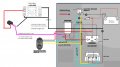
Thank you @MisterBill2. Please confirm if I understood correctly how-to wire 5pin relay for my needs, see file "new.jpg". Research tells me pin#86 once activated will then energize pin#87 which then I can use to start timer A103-006.
pin#85 goes to my ground or 12v-. I want an open state fed into A103-006 thus why I will leave pin#30 open. With relay, I will use my "HOT" signal to power pin#86, as fed voltage from the DOWN mode from switch, aka purple wire spliced into yellow. At least now I will have a true "OFF" state into the A103-006. Also, A103-006 has a reset function so I can zero-out after each use. Agree with my wiring? Also confirm one other research please, now that I'm feeding off of DOWN mode I will need module A17, FYI it attaches to the back of my A103-006, since my voltage will be above 5V?
A wiring diagram is much harder to evaluate than a circuit schematic diagram!!
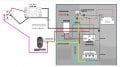
Not correct!! That might work, maybe, but the intention was for the two new connections be across the motor. That is the place where the polarity gets reversed, depending on the direction selected. And the relay contact connection is missing a connection to the other side of the contacts. That would be terminal 30, I think. The contacts within the relay are #30 is the moving contact, #87 is the normally open contact, and #87A is the normally closed contact. The ciol terminals are totally isolated from the contact connections.
The connections to the timer in that PDF do not seem to be similar to the connections shown in much earlier post, with the start connection being between terminals #1 and #3. Also, that PDF references 115 volt AC all over, and I am thinking this project was 12 volts DC powered.
 Facebook
 Google
 GitHub
 Linkedin