Zero-standby smart top-up charger for 24 V 120 Ah LiFePO4 (Codi) — 25–35 years battery life

Thread Starter

al11311

Joined Nov 22, 2025
6
I have a Codi (can by something else) 24 V 120 Ah LiFePO4 pack in standby (self-discharge ~1–2 % per month). Goal: keep it at 58–64 % SoC forever, charge only once every 1–3 months for 20–60 min, ~0 W from grid 99.99 % of the time.

Main aims:
1. Battery life-cycle should be maximized
2. Minimum energy consumption
3. System should be automatic for charging and as UPS

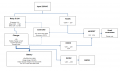
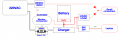
Current planned setup is on the fig.

What exact charger specifications are critical for the gentlest possible charging?
  • voltage/current accuracy
  • ripple
  • soft-start
  • tail-current cutoff
  • no float stage, etc.
Who is already running a similar “set-and-forget” top-up system for years? What controller + relay combo proved to be the most reliable?
Any suggestions how to improve the system or probably something is missed?
 

Attachments

Tonyr1084

Joined Sep 24, 2015
9,744
I've redrawn your flow chart so I could make better sense of what you need.
View attachment 359301
In your flow chart you show the AC/DC 220VAC to 12VDC going to a MOSFET and back to the controller. You show your controller being controlled by both 12V and 24V. My chart omits this along with the MOSFET. Instead of the MOSFET, since you have two sources of differing voltages (220 to 12 and 24 to 12) a simple diode arrangement would supply power to your small consumers. As for controlling the relay - you asked for it to charge the battery:
once every 1–3 months for 20–60 min.
A LiFePo battery can sit charged for years without needing to be recharged. But since you want to power two buck converters (one at 24 to 12 and one at 24 to 20 volts) they would be active at all times. It's doubtful your battery would support those converters for that long a period of time. As for the controller in your diagram it would likely draw next to nothing for current when not active.

What I've done is substituted your controller for a window comparator. You can set your upper charge limit at (and I'm guessing) 95% of full battery charge and a lower limit of (again I guess) 80%. This way when your battery voltage drops to a set voltage the charger comes on. When the battery reaches a full charge it shuts off. It will do that whenever there's a need. When the battery voltage is within the window the relay remains unactivated.

Well, that's my thought on the subject.
 

schmitt trigger

Joined Jul 12, 2010
2,056
I would use one of those ultra-low-power RTC and microcontroller, and every first of the month, or any number day you choose, wake up the charger to top the battery pack.
Since you will be using a microcontroller, you could choose to charge only on odd-months or whatever time algorithm you want.
 

Tonyr1084

Joined Sep 24, 2015
9,744
I would use one of those ultra-low-power RTC and microcontroller, and every first of the month, or any number day you choose, wake up the charger to top the battery pack.
Since you will be using a microcontroller, you could choose to charge only on odd-months or whatever time algorithm you want.
I have a question for you - do you think the battery would not drop below 20 volts sitting idle while running those buck converters?
I would agree that a BMS is required to prevent both overcharging and under voltage situations.
 

Tonyr1084

Joined Sep 24, 2015
9,744
I've amended my diagram to include a BMS (Battery Management System) to control charge rate and limit lower end voltage dropout. If the battery voltage drops below a set limit the relay will not come on. In that case you'd need a bypass switch to start the charging cycle manually. I have not included that in my diagram. Also, to avoid confusion I've moved the 220 VAC source to reflect that it's not on a different line.
View attachment 359305
 
Last edited:

Thread Starter

al11311

Joined Nov 22, 2025
6
You show your controller being controlled by both 12V and 24V
Not exactly, let me explain what I meant in my chart:
1. The controller takes 12V from common 220V input power grid. If no power in the grid -> no possible to charge -> nothing to control.
2. The controller connected to a battery only for measurements, no energy should be taken.
3. The controller needs only allow charge till ~64%, once ~64% is done - just turn off. And do nothing when charge is more than ~58%. If it comes to ~58% slowly or when no electricity comes to 50% - its a reason to start charging.
4. The controller handles upper limit. BMS required only to protect a battery for drop down less than 50%.

A laptop will be connected manually, only if required. Whereas small consumers (e.g. router) should/can be under UPS.

Only 3 consumers in waiting mode:
1. The controller - should be less 0.05 Wt = 36-50 Wt per month
2. Battery self-discharge = 50-80 Wt per month
3. Charging fees in relay and charger device = up to 10 Wt
 

Attachments

Thread Starter

al11311

Joined Nov 22, 2025
6
Scroll down to FAQ's for some good pointers on proper charge levels
Exactly! That’s why I want to control the charging level very precisely. Please refer to the figure in the link and my annotations. From the charts, it’s clear that the controller should be accurate to 0.01V. Additionally, the 20V–29.2V range is specified in the battery manual.

ultra-low-power RTC and microcontroller
Yes, that possible, can be considered as improvement, but I’m not sure how stable it will be if the battery will be turned off by BMS low voltage protection.

In general, this approach can be used?
 

Attachments

Tonyr1084

Joined Sep 24, 2015
9,744
In both of our drawings the battery voltage is directly sensed. However, the controller will need to be powered somehow. In my version I assumed the battery voltage would both provide power AND sense the battery voltage for the controller to operate. I understand your change to powering the controller via the main line power. In your version the lead from the battery to the controller is only for sensing the voltage. But are you sure about your numbers? 58% and 64% seem like exceptionally low numbers.
3. The controller needs only allow charge till ~64%, once ~64% is done - just turn off. And do nothing when charge is more than ~58%. If it comes to ~58% slowly or when no electricity comes to 50% - its a reason to start charging.
Not sure what you mean 36-50 Wt per month. "2. Battery self-discharge = 50-80 Wt per month" as well as "3. Charging fees in relay and charger device = up to 10 Wt" are also terms and references I'm not familiar with.
Only 3 consumers in waiting mode:
1. The controller - should be less 0.05 Wt = 36-50 Wt per month
2. Battery self-discharge = 50-80 Wt per month
3. Charging fees in relay and charger device = up to 10 Wt
Are you saying you expect your battery to drain up to 50 watts per month? That's a lot of power. 50W (watts) divided by 24V (average) equals 2.08 amps over the month. Is that standby or the average consumption of power?

You DID say you want this to charge every one to three months. At those power drain levels and desired period of charge cycles, that must be a very very big battery. Don't recall you mentioning anything about the type or size of the battery other than 24V LiFePo type. No mention of amp-hour rating of the battery. See edit below:

As for the BMS; if it shuts down then no power is available for use or for battery voltage sensing. In a condition like that the controller will sense "No Voltage" and assume that to be "Zero Volts". If line power is available the controller should turn on and charge the battery. So - yes - your version drawing control voltage from the main line is practical and wise.

What is "SP" and "MS"? It's obvious that MS is a switch or plug of some sort. But again, understand that even if the laptop is not connected the 24V/20V buck converter will still be drawing power. That and the 24VDC/12VDC buck converter, both draining the battery even when no power is being used.

Just want to be sure I understand what your goal is and whether you've considered all things relevant to the project.
Your first diagram shows AC/DC ~220V —> 12V and DC/DC 24V —> 12V 1-2A feeding a MOSFET of some sort. Your second version does away with the FET. Is that intentional?

BTW: Excellent job modifying my diagram.

[edit] OOPS! Just noticed the battery size in your title "24V 120AH LiFePo4". That's a fairly large battery. But still, that can still be drained by all the active components in the circuit. [end edit]
 
Last edited:

Thread Starter

al11311

Joined Nov 22, 2025
6
Not sure what you mean 36-50 Wt per month. "2. Battery self-discharge = 50-80 Wt per month" as well as "3. Charging fees in relay and charger device = up to 10 Wt" are also terms and references I'm not familiar with.
Energy consumption in Watt-hours over a month/30 days:
1. Controller and P-MOSFET: < 50 Watt-hours per 30 days - constant consumption 24/7
2. Battery self-discharge: According to articles, around 1-2% per 30 days, so 3000 * 0.02 = 60 Watt-hours - constant consumption 24/7
3. Charging fees in relay and charger device: About 10 Watt-hours - only during 20-60 minutes of charging

What is "SP" and "MS"?
That were my internal notes, which I forgot to remove, "Small Power" and "Manual Switch"

Just want to be sure I understand what your goal is and whether you've considered all things relevant to the project.
Your first diagram shows AC/DC ~220V —> 12V and DC/DC 24V —> 12V 1-2A feeding a MOSFET of some sort. Your second version does away with the FET. Is that intentional?
Right, thanks! Good point, FET is missed and DC/DC adapters take some energy permanently. Thus, they should be hidden after a P-MOSFET.
Once we have 12V signal from main line, P-MOSFET will not allow for ~24V flow. If no electricity, then no 12V signal to P-MOSFET and ~24V line becomes available.
Updated the fig.

BTW: Excellent job modifying my diagram.
Thank you! :)))

Scheme2.1.png
 

Thread Starter

al11311

Joined Nov 22, 2025
6
I did some reading and selected a few components:

1. Will a P-MOSFET transistor such as the IRF9540NS / IRF9540N / IRF9540PBF work for the UPS part? When the mains power is lost, the control signal will stop being applied to it, and it will open the path from the battery and immediately switch the router’s power to the battery.
https://www.infineon.com/part/IRF9540NS

2. The TE Connectivity 5-1393243-2 (RT424F05) relay — this is a bistable relay that doesn’t consume power in either state, only during switching, correct? Will this type work?
https://www.tme.eu/en/details/rt424f05/miniature-electromagnetic-relays/te-connectivity/5-1393243-2/

3. I'm going to control this relay (it has two control pins: one for ON and one for OFF) using an Arduino Pro Mini — very low power consumption, especially when sleep() function called.
https://docs.arduino.cc/retired/boards/arduino-pro-mini/
https://forum.arduino.cc/t/328p-pro-mini-power-consumption/1060993/4
https://www.gammon.com.au/power

Later I will check for a charging device and AC/DC, DC/DC
 

Irving

Joined Jan 30, 2016
5,068
I think you're being overly cautious. 1 - 2% a month self discharge seems excessive. I have a 100Ah 24v LFP pack that I bought in Feb 2018. SoC when it arrived was 40%, after 18 months storage in my office it had lost just 3%. Since then its been in constant use, charged to 80% and discharged to 30% every 14 days or so, float charged at 1/20C (5A), and actively balanced. Every year I do a capacity check from 100% to 20% at 1/10C (10A) and, to date, after nearly 7 years there has been no measurable change in capacity - they'll easily last 15y+. Given I paid nearly £900 for them and can now be had for under £270 I'm not worried about lifespan - they're a commodity item now.
 
Top