
Zener Diodes in series as Voltage Regulators

MisterBill2

Joined Jan 23, 2018
27,777
Yes, true but I would have to manually adjust the output voltage each time I wanted to move to a much higher value before connecting the correct circuit (to match the component values), wouldn't I?
One adjustable regulator with a switch to bypass one or two or NONE. By having the switch bypass instead of select, there will be no interval with no programming resistance, and thus no unfortunate transients. And only one regulator providing the three preset voltages. So only one driver required. And no loss of the functions requested.
As for frequencies, the square wave has a very long string of odd harmonics, and, unfortunately, square waves and transformers do not play nicely, especially as the frequency increases.
The really bad news is that the emitter follower amplifier shown in the earlier post will not come close to delivering a square wave because the RC portion will convert it into a curved RC time constant shape of sawtooth wave.
 
Last edited:
Thread Starter

Gumnuts

Joined Apr 26, 2024
35
One adjustable regulator with a switch to bypass one or two or NONE. By having the switch bypass instead of select, there will be no interval with no programming resistance, and thus no unfortunate transients. And only one regulator providing the three preset voltages. So only one driver required. And no loss of the functions requested.
As for frequencies, the square wave has a very long string of odd harmonics, and, unfortunately, square waves and transformers do not play nicely, especially as the frequency increases.
The really bad news is that the emitter follower amplifier shown in the earlier post will not come close to delivering a square wave because the RC portion will convert it into a curved RC time constant shape of sawtooth wave.
Hmm, THat would be a problem. I wanted the Frequency Generator to not provide all the current for the rest of the circuit, hence the buffer. Any suggestions to what could be used to preserve the square wave instead?
 

Thread Starter

Gumnuts

Joined Apr 26, 2024
35
Certainly the zener diode/resistor stack is an interesting concept, but it does not work if any current is drawn.
What I missed was a description of the intended purpose of the whole project. The description in post #1 does not mention the overall purpose, but only the intent of the portions discussed.

My guess is that the ultimate intent is to apply different voltage pulse strings to the capacitor not described, but shown, in post #1.
Aside from the issue of the different voltages to the CMOS oscillator circuits, I did not see any serious goofs.
But certainly the system could be much less complex.
At the 10 KHz frequency the transformer driving the capacitor charging circuit will not be a common, iron cored device, if efficiency is any consideration. And quite likely the amplifier circuit will be more complex.
Previously I used a coil with a non-permanent magnet core, ferrite, with only a primary and secondary winding to deliver a 10 fold increase.,
 

Thread Starter

Gumnuts

Joined Apr 26, 2024
35
What is this project supposed to measure ?
Shades of Stan Meyer come to mind.
Are You looking for the "Resonant-Frequency" of your "Capacitor" ?
An Output Transformer adds all kinds of complexities.
.
.
.
Previously I used a coil with a non-permanent magnet core, ferrite, with only a primary and secondary winding to deliver a 10 fold increase.,
 

MisterBill2

Joined Jan 23, 2018
27,777
Many audio amplifiers provide good frequency response and low distortion, and some are not very complex. What is unknown to us is how much actual power is required for this application. Driving capacitor charging does require power, not just voltage.
(I offer no opinion as to the purpose of the research, only a solution to the technical challenge.)
 

Thread Starter

Gumnuts

Joined Apr 26, 2024
35
Boy, T am so appreciative of your comments!
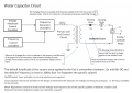
I created this circuit 30 years ago but I haven't designed circuits for the over 20 years now. So I approached 3 different design houses over the last couple of months to create one with the Block diagram below.
All 3 said the job 'is just too small for us' and couldn't in all faith charge their minimum fee to develop the schematics/card for me (between $5K and $15K just to start). So I'm left attempting to create it myself, I can do many things but I do need some help.
Again, thank you! And the transformer has a toroidal core.

1714306865063.png
 
Last edited:

Thread Starter

Gumnuts

Joined Apr 26, 2024
35
Many audio amplifiers provide good frequency response and low distortion, and some are not very complex. What is unknown to us is how much actual power is required for this application. Driving capacitor charging does require power, not just voltage.
(I offer no opinion as to the purpose of the research, only a solution to the technical challenge.)
Post Number #27 was meant for you. :) Sorry, I'm not used to Forums
 

MisterBill2

Joined Jan 23, 2018
27,777
If you can get the use of an oscilloscope for a bit, I suggest looking at the voltage actually applied to the capacitor, and compare that to what you are wanting to apply. I suspect there will be a difference.
And Thank You for the description of the transformer, not at all like I was thinking, it is much more suitable for high frequency, like you are using, than I had thought. Certainly not a common type for audio use. Definitely a higher frequency transformer.
 

Thread Starter

Gumnuts

Joined Apr 26, 2024
35
Where there is a will, there is a way. There are some little cro type units for diagnosing car electronics I've been looking at.
I can see that hysteresis will be another possible issue. I can't resolve much without some electronic device to drive my capacitor.
 

Thread Starter

Gumnuts

Joined Apr 26, 2024
35
If you can get the use of an oscilloscope for a bit, I suggest looking at the voltage actually applied to the capacitor, and compare that to what you are wanting to apply. I suspect there will be a difference.
And Thank You for the description of the transformer, not at all like I was thinking, it is much more suitable for high frequency, like you are using, than I had thought. Certainly not a common type for audio use. Definitely a higher frequency transformer.
Would it be inappropriate to ask what type of components would you start with??
 

MisterBill2

Joined Jan 23, 2018
27,777
It may be that you do not need to have a resistor and capacitor in series with the coil, if the duty cycle is adjusted so that the transformer does not spend time in the saturated magnetic field region.
My whole point was that while you know what sort of voltage wave form you want, that may not be what you are actually getting. And since it appears that you do have a specification in mind, verifying that it is what you intend will be an important part of validating your results.

My concern is that the normal process for discoveries to be validated and accepted is usually done by publishing the process so that others may get similar results. And my guess is that the TS has a theory to verify using this system, to produce some sort of results that verify the theory. (That is the standard scientific method).
Validation then comes from others being able to achieve the same results using the same methods, and publishing that result.
 

Thread Starter

Gumnuts

Joined Apr 26, 2024
35
It may be that you do not need to have a resistor and capacitor in series with the coil, if the duty cycle is adjusted so that the transformer does not spend time in the saturated magnetic field region.
My whole point was that while you know what sort of voltage wave form you want, that may not be what you are actually getting. And since it appears that you do have a specification in mind, verifying that it is what you intend will be an important part of validating your results.

My concern is that the normal process for discoveries to be validated and accepted is usually done by publishing the process so that others may get similar results. And my guess is that the TS has a theory to verify using this system, to produce some sort of results that verify the theory. (That is the standard scientific method).
Validation then comes from others being able to achieve the same results using the same methods, and publishing that result.
I hear you but I'm old as I said. I want to prove it again myself first, hence building the circuit. I know what want to achieve, I know most of the parameters I used back then, and I have two physical scientific tests to determine if the capacitor circuit achieves the same results I achieved 30 years ago, (those same tests didn't exist 30 years ago). I'm keen to proceed but rocks and hard places come to mind.
 

Thread Starter

Gumnuts

Joined Apr 26, 2024
35
I hear you but I'm old as I said. I want to prove it again myself first, hence building the circuit. I know what want to achieve, I know most of the parameters I used back then, and I have two physical scientific tests to determine if the capacitor circuit achieves the same results I achieved 30 years ago, (those same tests didn't exist 30 years ago). I'm keen to proceed but rocks and hard places come to mind.
Oh, The Capacitor build will be completed by end of next week.
 
Top




