Facebook
 Google
 GitHub
 Linkedin
As max said, the inrush current for a electric motor of that design is pretty high.Thanks Dave, I looked at the link, and I see that the triacs shown are all heavier than the BT137 - but you say "Several triacs available". The BT137 was also one of several available. I figured that at 240V RMS, 8A, it should be capable of driving about 1920W, which is 2.5HP - and as the plate on the motor says "1.72A; 370W", I thought I'd be OK with that triac. I therefore repeat my question - would you have expected this triac to instantly pop? If so, can you explain why it was a bad choice?
I'm not disputing what you say, Dave - for me, it's a learning experience, and I came here because it's a room full of people who know better than I.
Theoretically extramly high given such a motor may have an equivalent series resistance of ~3 ohms and one a 240 VAC supply system with a peak voltage of ~340 volts that equates to a theoretical inrush current of ~115 amps. In reality all the various line voltage losses in the supply wiring will at least cut that in half but still in electronics terns a I would not be using anything rated for less than 120 amps peak current and 20 - 30 continuous.
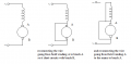
Now for bonehead simple soft starting (old school series resistance current limiting soft starter) you could get by with as little as a properly sized resistor and a relay set up.
All you would need is a realy with a AC coil that is rated for your line voltage and resistor that when inserted with the motor limits the motors input voltage at no load to something just above whatever voltage the relay will pull in at.
The resistor is wired across the normally open contacts of the relay and the relay coil is wires in parallel with the motor so that when the power is first applied the resistor works as a current limiter until the motor gets up to speed far enough for the voltage across it and the relay coil to get high enough for the relay to close its contacts and bypass the resistor thus putting full line power to the motor.
Most 240VAC rated relays will pull in at around 180 - 200 volts if not less so all you would need to do is size your resistor to let the motor have enough current at no load to get its voltage up at least that high.